Troubleshooting Guide Bushing Wear in CNC Swiss Machining
Diagnose and fix guide bushing wear, spindle vibration, and bar feed sync errors in CNC Swiss machining with this expert troubleshooting guide.
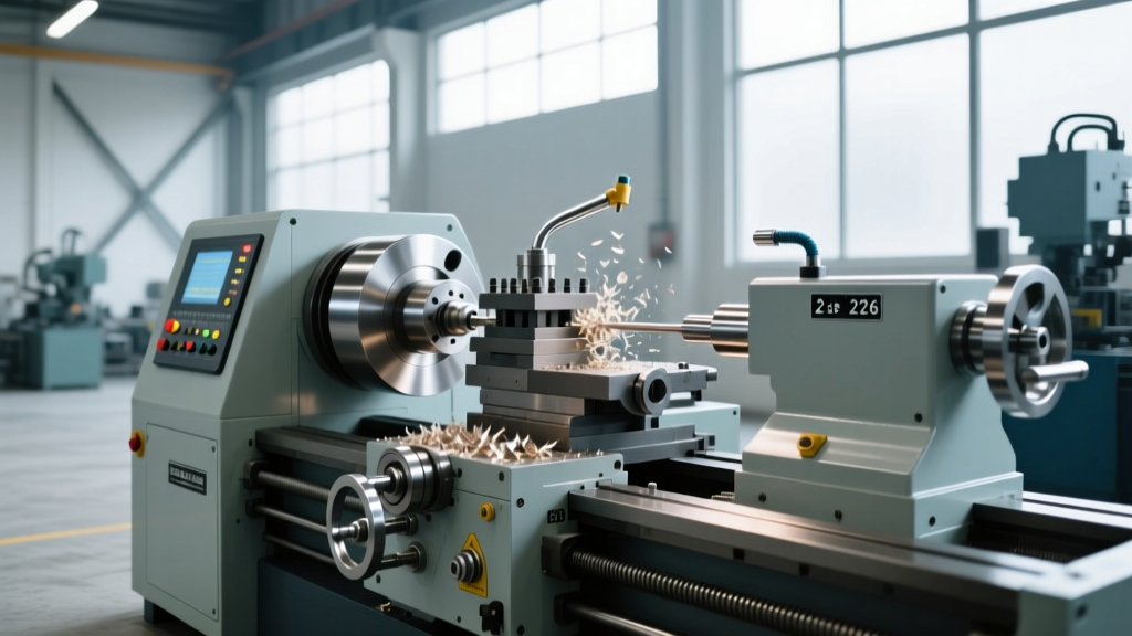
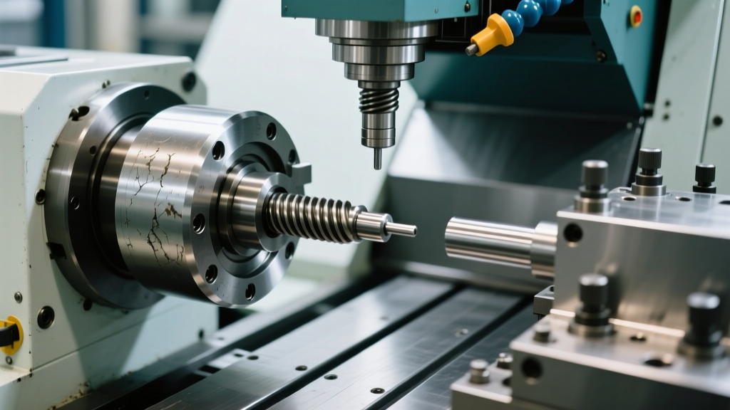
The defining characteristic of CNC Swiss machining is the sliding headstock and stationary guide bushing. Unlike conventional lathes where the spindle rotates and the tool moves, Swiss-type machines feed the bar stock through the guide bushing while the cutting tools operate within millimeters of the support point. When the guide bushing degrades, the entire kinematic foundation of the machine collapses, resulting in harmonic chatter, dimensional tapering, and catastrophic sub-spindle transfer crashes.
The Anatomy of Guide Bushing Failure in Swiss-Type Lathes
In modern machines like the Tsugami B0125 or Citizen Cincom L20XII, the guide bushing maintains a radial clearance of just 0.0002 to 0.0005 inches (0.005mm to 0.012mm) against the raw bar stock. This microscopic gap is flooded with high-speed lubricant to create a hydrodynamic wedge. Failure rarely occurs from normal abrasive wear alone; it is almost always precipitated by lubrication starvation, particulate ingress, or thermal expansion mismatches.
CRITICAL LUBRICATION WARNING:Never substitute standard way oil or lithium-based spindle grease in the guide bushing assembly. The hydrodynamic film required at 10,000+ RPM demands a low-viscosity, high-oxidation-stability fluid. Using ISO VG 32 way oil instead of the specified ISO VG 10 spindle oil (such as Mobil Velocite Oil No. 6) will cause localized boiling, carbon scoring on the carbide bushing liners, and immediate seizure of the bar stock.
Diagnostic Matrix: Differentiating Bushing Wear from Tooling Issues
Operators frequently mistake guide bushing wear for worn carbide inserts or incorrect feeds and speeds. Before scrapping expensive tooling or rewriting CAM code, cross-reference your machine's symptoms against this diagnostic matrix.
| Symptom | Frequency / Indicator | Root Cause | Corrective Action |
|---|---|---|---|
| High-pitch harmonic chatter on long shafts | 8,000 - 12,000 Hz acoustic signature | Radial clearance exceeds 0.0015"; hydrodynamic film collapse | Replace bushing liners; verify bar stock centerless grind tolerance (+0/-0.0004") |
| Tapering on OD turning operations (>20mm length) | Dimensional drift of 0.0005" per inch of Z-travel | Uneven bushing wear causing bar stock to deflect away from the cutting tool | Adjust bushing clamping pressure; inspect for chip packing in the front seal |
| Fanuc Alarm 411 (Z-axis following error) during bar feed | Occurs exactly at the Z-axis rapid traverse phase | Excessive friction inside the bushing fighting the main spindle Z-axis servo motor | Flush bushing with solvent; check lube pump pressure (must be >15 psi at nozzle) |
| Sub-spindle transfer crashes or misalignment | Sub-spindle alarms upon closure; part pushed off-center | Worn bushing allows main spindle to push part out of concentricity during cutoff | Rebuild guide bushing; re-teach sub-spindle pick-up position with dial indicator |
Step-by-Step: Rebuilding the Guide Bushing Assembly
Replacing the guide bushing on a Swiss-type lathe is not a simple drop-in procedure. The concentricity of the bushing to the main spindle Z-axis slide must be maintained within 0.0002 inches. Follow this procedure to ensure proper alignment.
- Isolate and Clean: Execute Lockout/Tagout (LOTO). Remove the front sliding cover and disconnect the high-pressure coolant and lubrication lines. Use lint-free wipes and acetone to clean the external housing to prevent chip ingress during disassembly.
- Extract the Retaining Nut: Using the manufacturer-specific spanner wrench (e.g., Citizen tool #T89-001), loosen the front retaining nut. Note: These are often left-hand threaded on specific Tsugami models to prevent loosening during reverse spindle rotation. Verify thread direction before applying force.
- Remove the Bushing Cartridge: Slide the cartridge out of the Z-axis housing. Inspect the inner carbide liners for scoring. If you see longitudinal grooves deeper than 0.0001 inches, the bar stock diameter tolerance was too loose, or the material was out-of-round.
- Verify Housing Runout: Mount a 0.0001-inch resolution dial indicator on the machine bed. Sweep the inside bore of the Z-axis housing. If runout exceeds 0.0003 inches, the Z-axis slide bearings may be compromised, and replacing the bushing will only provide a temporary fix.
- Install and Torque: Insert the new bushing cartridge. Hand-tighten the retaining nut, then use a calibrated torque wrench to tighten to exactly 42 Nm (for standard 20mm capacity machines). Overtorquing will distort the carbide liners, creating a 'pinch point' that will gall the bar stock immediately upon startup.
- Dynamic Runout Check: Insert a certified ground test bar (exact nominal diameter, e.g., 20.000mm). Close the bushing clamping mechanism. Rotate the bar by hand and sweep the exposed tip with the dial indicator. Acceptable runout is less than 0.0004 inches TIR (Total Indicator Reading).
Resolving Bar Feeder Synchronization and C-Axis Errors
A major advantage of advanced CNC Swiss machining is the integration of hydrostatic or servo-driven bar feeders (like the IEMCA Boss 542 or LNS Alpha). However, the mechanical coupling between the bar feeder pusher and the main spindle collet introduces complex synchronization variables.
C-Axis and Main Spindle Phase Alignment
When performing off-center drilling or cross-milling with live tooling, the main spindle must lock into the C-axis. If the guide bushing is worn, the rotational inertia of the bar stock causes micro-slippage inside the bushing during the C-axis brake engagement. This results in angular misalignment of the cross-drilled holes. To troubleshoot this, verify the C-axis brake engagement pressure in the machine's PMC (Programmable Machine Controller) parameters. For Fanuc 31i-B controls, parameter #4000 series dictates the spindle orientation speed and brake torque. Increasing the brake torque by 15% can often overcome minor bushing slippage without requiring an immediate teardown.
PRO-TIP: Collet Pull-Back TensionThe main spindle collet must exert enough force to pull the bar stock back against the internal stop, but not so much that it deforms the material. For 12L14 free-machining steel, set the collet draw-tube pressure to yield a 0.005" to 0.008" pull-back. For softer materials like 303 Stainless or 6061 Aluminum, reduce pressure to achieve a 0.002" pull-back to prevent the collet from biting into and scoring the bar surface, which subsequently accelerates guide bushing wear.
Sub-Spindle Transfer: The Ultimate Bushing Wear Test
The most unforgiving operation in Swiss machining is the sub-spindle transfer. As the main spindle pushes the partially machined part forward for the cutoff operation, the sub-spindle approaches to catch it. According to Sandvik Coromant's turning guidelines, maintaining concentricity between main and sub-spindles is critical for avoiding tool breakage and part damage. If the guide bushing has even 0.001 inches of radial play, the cutting forces from the front-working tools will push the bar stock off-center. When the sub-spindle closes, it will grab the part eccentrically, causing a severe crash or triggering a Z-axis torque limit alarm.
To diagnose transfer issues related to the bushing, perform a 'dry transfer' test. Machine a part up to the cutoff point, but stop the machine before the cutoff tool engages. Manually jog the sub-spindle forward to close on the part. Use a feeler gauge to check the gap between the part OD and the sub-spindle collet pads. If the gap is uneven (e.g., 0.002" on top, 0.006" on the bottom), your guide bushing is worn, or the main spindle Z-axis slide is dropping due to worn linear guide blocks.
Preventative Maintenance Schedule for Swiss Guide Bushings
Relying on reactive maintenance for Swiss-type lathes guarantees scrap parts and unplanned downtime. Implement this strict, interval-based maintenance protocol to maximize bushing life, drawing on best practices outlined by the Kennametal turning knowledge base regarding machine rigidity and tool life optimization.
- Daily (Start of Shift): Verify guide bushing lube reservoir level. Purge the lube line manually via the operator panel to ensure oil is physically reaching the front seal. Wipe the exposed bar stock with a solvent-soaked rag to remove mill scale and coolant residue before it enters the bushing.
- Weekly: Inspect the front chip wiper seal. If the rubber lip is curled or torn, replace it immediately. A failed wiper allows abrasive swarf (especially from titanium or Inconel) to pack into the bushing clearance gap.
- Monthly: Check the bar feeder pusher collet for wear. A worn pusher collet allows the bar to vibrate axially, creating a 'hammering' effect inside the guide bushing that spalls the carbide liners over time.
- Bi-Annually (Every 1,000 Spindle Hours): Completely disassemble, ultrasonically clean, and inspect the guide bushing cartridge, regardless of apparent machine performance. Replace the internal O-rings and thrust bearings as a matter of standard procedure.
Mastering the mechanical nuances of the guide bushing separates average Swiss shops from elite medical and aerospace suppliers. By treating the bushing as a precision hydrodynamic bearing rather than a simple wear item, machinists can hold sub-micron tolerances and eliminate the harmonic chatter that plagues high-volume production environments.