Lathe Machine CNC Troubleshooting: Fixing Chatter and Taper Errors
Diagnose and fix common lathe machine CNC issues. Step-by-step repair guides for eliminating tool chatter, correcting tailstock taper, and tuning servos.
Unplanned downtime on a lathe machine CNC setup costs modern job shops an average of $150 to $300 per hour in lost spindle time and scrap material. When surface finish degrades or dimensional tolerances drift, operators often default to reducing feed rates—a reactive measure that kills cycle times without addressing the root cause. This guide provides advanced diagnostic frameworks for resolving harmonic chatter, Z-axis taper, and servo following errors on modern turning centers equipped with Fanuc 31i-B5 or Haas NGC controls.
Diagnostic Decision Tree: Symptom to Root Cause
Before adjusting offsets or swapping inserts, map the physical symptom to the mechanical subsystem. Use this decision matrix to isolate the failure point:
- Symptom: High-frequency ringing noise, regenerative surface waves. Subsystem: Spindle bearings, toolholder L/D ratio, or insert geometry. Action: Proceed to Harmonic Chatter Protocol.
- Symptom: Parts measure larger at the tailstock end than the chuck end. Subsystem: Tailstock alignment, Z-axis gib wear, or thermal growth. Action: Proceed to Taper Elimination Protocol.
- Symptom: Contouring errors, ovality on bored IDs, or servo alarms. Subsystem: Axis servo tuning, ball screw backlash, or way lubrication. Action: Proceed to Servo Drift Protocol.
Protocol 1: Eliminating Harmonic Tool Chatter
Chatter is a self-excited vibration caused by the dynamic interaction between the cutting tool and the workpiece. On a lathe machine CNC configuration, it typically manifests when the depth of cut (DOC) exceeds the dynamic stiffness of the toolholding system.
Toolholder Overhang and L/D Ratios
The most common mechanical culprit is an excessive Length-to-Diameter (L/D) ratio on the boring bar or turning tool. For standard steel shanks, the maximum stable L/D ratio is 3:1. If your application requires a 4:1 or 5:1 overhang, you must upgrade to a solid carbide boring bar (stiffness increases by roughly 300%) or an anti-vibration bar with a tuned mass damper (e.g., Sandvik Coromant Silent Tools). According to the Sandvik Coromant turning knowledge base, damping systems can increase metal removal rates by up to 50% in deep-boring operations by absorbing harmonic frequencies before they transfer to the workpiece.
Insert Geometry and Speed Mapping
If the tooling is rigid but chatter persists, the issue lies in the cutting edge geometry and spindle speed.
- Reduce Nose Radius: A 1/32" (0.8mm) nose radius generates lower radial cutting forces than a 1/16" (1.6mm) radius. Switch to a smaller radius for finishing passes.
- Positive Rake Angles: Use inserts with a sharp, positive rake geometry (e.g., DNMG 331 instead of DNMG 432) and a finishing chipbreaker (like the Kennametal FP or Sandvik MF) to shear the material rather than plowing it.
- RPM Tuning: Chatter is speed-dependent. Use a tachometer or the control's spindle load meter to find the stable RPM window. Increasing or decreasing the spindle speed by 10-15% often shifts the process out of the resonant frequency band.
If chatter occurs across multiple tools and speeds, the main spindle bearings may have lost preload. Mount a 0.0001" dial indicator on the tool turret and push against the spindle nose with 15 lbs of force. Deflection exceeding 0.0003" indicates bearing wear. Re-shimming the bearing stack requires a certified technician and typically costs between $2,500 and $4,500 depending on the machine model.
Protocol 2: Correcting Z-Axis Taper and Tailstock Misalignment
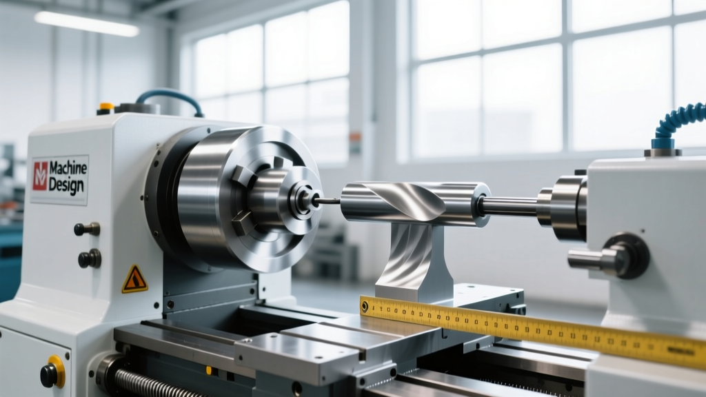
When turning long shafts between centers, a lathe machine CNC setup relies on perfect alignment between the headstock spindle centerline and the tailstock quill centerline. Even a 0.001" misalignment will produce a measurable taper over a 6-inch cut. Additionally, excessive hydraulic chuck pressure can cause thin-walled parts to deform, creating a tapered bore once the clamping force is released. Always verify clamping pressure (typically 300-450 PSI for standard 8-inch chucks) before assuming mechanical misalignment.
The Twin-Indicator Test Bar Method
Do not rely on the engraved scale on the tailstock base; these are only accurate to roughly 0.010" and are useless for precision CNC work. Follow this exact procedure:
- Mount a precision ground 1.000" diameter test bar (at least 8 inches long) between the headstock and tailstock centers.
- Mount two dial indicators (0.0001" resolution) on the cross-slide, spaced exactly 4.000" apart along the Z-axis.
- Zero both indicators on the front (X-axis) of the test bar.
- Rotate the spindle 180 degrees and read the indicators on the back side of the test bar.
- Calculate the delta between the two indicators. The required tailstock offset is exactly half of this delta value.
| Indicator Delta (Over 4") | Taper per Inch | Required Tailstock Offset | Adjustment Direction |
|---|---|---|---|
| 0.0020" | 0.0005" / inch | 0.0010" | Toward Operator (if larger at tailstock) |
| 0.0040" | 0.0010" / inch | 0.0020" | Toward Operator |
| -0.0020" | -0.0005" / inch | 0.0010" | Away from Operator (if smaller at tailstock) |
Cast iron and steel machine beds expand as they heat up. A cold machine will cut a different taper than one that has been running for 4 hours. Always perform the twin-indicator test after the machine has completed a 30-minute warm-up cycle (spindle at 1500 RPM, axes moving rapidly). Modern Haas NGC controls feature thermal compensation parameters, but physical tailstock alignment remains the baseline requirement. For more on Haas thermal settings, refer to the Haas Automation Tech Tips portal.
Protocol 3: Servo Following Errors and Axis Drift
If your lathe machine CNC system throws following error alarms (e.g., Fanuc Alarm 411) or produces out-of-round bores during circular interpolation, the issue is servo mismatch or mechanical binding.
Ballbar Diagnostics
Use a telescoping ballbar system, such as the Renishaw QC20-W, to map the X-Z plane. The software will generate a polar plot that visually identifies the mechanical fault:
- Cloverleaf Pattern: Indicates servo mismatch. One axis is responding faster than the other. Adjust the velocity loop gain (Fanuc Parameter 2021) on the lagging axis in 5% increments until the plot circularizes.
- Oval Plot Tilted at 45 Degrees: Indicates backlash in the ball screw or excessive play in the thrust bearings. Check the Z-axis thrust bearing preload (typically requires 150-200 ft-lbs on the lock nut for a 40mm ball screw).
- Flat Spots on Axis Transitions: Indicates static friction (stiction). Verify that the way lube system is delivering the correct volume (usually 2-4cc per shot) of ISO 68 way oil (such as Mobil Vactra No. 2) and that the metering units are not clogged with degraded oil.
Preventative Maintenance Matrix for Turning Centers
To prevent these issues from recurring, implement this strict maintenance cadence. Neglecting way lube or coolant concentration directly accelerates the mechanical wear that causes chatter and taper.
| Interval | Component | Action Required | Target Spec / Tolerance |
|---|---|---|---|
| Daily | Way Lubrication | Check reservoir level, verify pressure switch cycles | 15-20 PSI system pressure |
| Weekly | Coolant Concentration | Test with refractometer, adjust tramp oil skimmer | 8% - 10% concentration |
| Monthly | Turret Curvic Coupling | Clean mating surfaces, check clamping pressure | Hydraulic pressure > 450 PSI |
| Bi-Annual | X and Z Axis Gibs | Adjust taper gibs to eliminate pitch/yaw play | < 0.0002" indicator play |
| Annual | Ball Screw End Play | Measure axial float with dial indicator | < 0.0001" axial movement |
Resolving dimensional and surface finish issues on a lathe machine CNC setup requires moving beyond trial-and-error offsets. By systematically isolating harmonic frequencies, mechanically verifying tailstock alignment to the ten-thousandth of an inch, and utilizing ballbar diagnostics for servo tuning, maintenance teams can restore machine geometry to factory specifications and eliminate costly scrap events.