Stainless Steel CNC Machining: Surface Finish & Tolerance Innovations
Explore how advanced stainless steel CNC machining achieves ultra-precise tolerances and mirror surface finishes using modern metrology and tooling tech.
The Metallurgical Bottleneck: Why Stainless Steel Defies Standard Tolerances
Austenitic stainless steels, particularly 304 and 316L, present unique challenges in contract machining due to their low thermal conductivity and high work-hardening rates. Unlike 6061 aluminum or 1018 mild steel, where heat dissipates efficiently into the chip, stainless steel retains up to 70% of its cutting heat at the tool-workpiece interface. This thermal concentration leads to rapid tool flank wear and dimensional drift, making standard ISO 2768-m tolerances (±0.005 inches) difficult to hold consistently over long production runs without advanced compensation strategies.
Martensitic and precipitation-hardened grades like 17-4PH introduce a different problem: extreme abrasiveness. The hard carbide precipitates in 17-4PH act like grinding compound against cutting edges, necessitating rigid 5-axis trunnion setups and specialized TiSiN (Titanium Silicon Nitride) coatings to maintain geometric dimensioning and tolerancing (GD&T) per ASME Y14.5-2018 standards.
Critical Alert: Built-Up Edge (BUE) FormationWhen machining 316L at incorrect surface feet per minute (SFM), the material will weld to the cutting edge, forming a Built-Up Edge. This alters the tool geometry in real-time, destroying surface finishes and causing catastrophic micro-chipping. To prevent BUE, maintain cutting speeds above 250 SFM with variable-helix solid carbide end mills and never let the tool dwell in the cut.
Redefining Precision: Tolerance Matrix for Production Machining
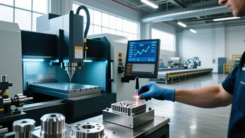
Achieving tight tolerances in stainless steel requires moving beyond standard 3-axis VMCs. Modern machine shops utilize closed-loop probing systems and AI-driven acoustic emission sensors to detect tool deflection at the micron level. Below is a practical tolerance matrix for high-volume stainless steel production.
| Material Grade | Standard VMC (ISO 2768-m) | Precision 5-Axis / Turn-Mill | Ultra-Precision (Jig Bore / Grind) | Primary Failure Mode |
|---|---|---|---|---|
| 303 (Free-Machining) | ±0.005 in (0.127mm) | ±0.001 in (0.025mm) | ±0.0002 in (0.005mm) | Porosity / Sulfur Inclusions |
| 304 / 316L (Austenitic) | ±0.005 in (0.127mm) | ±0.0015 in (0.038mm) | ±0.0003 in (0.007mm) | Thermal Expansion / Work Hardening |
| 17-4PH (Condition H1150) | ±0.004 in (0.101mm) | ±0.001 in (0.025mm) | ±0.0002 in (0.005mm) | Abrasive Tool Wear / Deflection |
According to Sandvik Coromant's material machining guidelines, achieving the 'Precision' tier for 316L requires through-spindle coolant (TSC) at a minimum of 1,000 PSI to effectively evacuate the gummy, stringy chips that cause recutting and subsequent tolerance degradation.
Surface Finish Metrology: The Shift from 2D Ra to 3D Sa Parameters
Historically, surface finish in CNC machining was specified using Ra (Arithmetic Average Roughness), a 2D stylus-based measurement. However, for critical fluid-handling components, medical implants, and aerospace fittings machined from stainless steel, Ra is no longer sufficient. The industry is rapidly shifting toward Sa (Areal Surface Roughness), which uses white-light interferometry to map a 3D topographical area of the surface.
A standard face-milled 304 stainless steel part typically yields a 125–250 µin (3.2–6.3 µm) Ra finish. By implementing trochoidal milling toolpaths with high-feed milling cutters, shops can reliably achieve a 32–63 µin (0.8–1.6 µm) Ra finish directly off the machine. For mirror finishes requiring <8 µin (0.2 µm) Ra, secondary processes like electropolishing or abrasive flow machining (AFM) are mandatory, as mechanical cutting alone cannot overcome the micro-tearing inherent to austenitic grain structures.
Next-Generation Toolpath and Coolant Strategies
- Dynamic Milling / Trochoidal Toolpaths: Maintains a constant radial engagement angle (typically 5-10% of tool diameter), preventing the heat spikes that cause thermal expansion in the workpiece.
- High-Pressure Through-Tool Coolant: Operating at 1,500 PSI, this creates a localized vapor barrier that cools the cutting edge while physically shearing the chip away from the rake face, essential for preventing BUE on 316L.
- Cryogenic Machining: For aerospace 15-5PH and 17-4PH components, liquid nitrogen (LN2) delivered directly to the cutting zone reduces localized temperatures by up to 40%, extending tool life by 300% and improving surface integrity by eliminating white-layer formation.
Cost-vs-Precision Decision Framework for Engineers
Over-specifying tolerances and surface finishes on stainless steel components is the leading cause of inflated production costs. Every additional decimal place of precision in stainless steel increases machining time and metrology costs exponentially. Use the following framework when drafting CAD models and 2D drawings:
'Unless a feature interfaces with a dynamic seal, a press-fit bearing, or an optical sensor, default to standard ISO 2768-m tolerances and a 125 µin Ra finish. Forcing a ±0.0005-inch tolerance on a 316L structural bracket simply drives up scrap rates without adding functional value to the assembly.'
To optimize your manufacturing metrology and quality assurance workflows, apply GD&T feature control frames selectively. Use true position and profile of a surface callouts only on critical mating interfaces, and rely on general profile tolerances for non-critical geometry. This allows the CNC machinist to prioritize spindle time and tool life on the features that actually dictate the part's mechanical performance.