Safety Compliance and CNC Machining Costs for Electronics Enclosures
Explore how IP67, EMI shielding, and MIL-STD compliance dictate tight-tolerance CNC machining costs for electronics enclosures, featuring DFM frameworks.
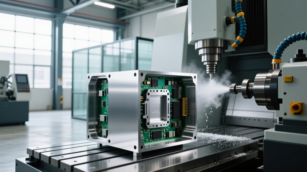
Designing electronics enclosures for aerospace, medical, or industrial IoT applications requires treating the housing not merely as a protective box, but as a critical life-safety and data-integrity barrier. When engineering teams design for compliance with IP67 ingress protection, MIL-STD-461 electromagnetic interference (EMI) shielding, or ATEX hazardous area directives, the manufacturing methodology shifts dramatically. These stringent safety standards mandate ultra-precise geometries, specialized surface finishes, and exotic alloys—all of which fundamentally alter cnc machining costs.
Understanding the exact mechanical and metallurgical requirements of these compliance standards is the only way to accurately forecast production budgets and implement effective Design for Manufacturability (DFM) strategies.
⚠️ Compliance Warning: Attempting to machine EMI gasket grooves or O-ring glands to standard commercial tolerances (±0.005") will almost certainly result in catastrophic failure during environmental or EMC certification testing, leading to scrapped batches and delayed product launches.The Tolerance-to-Cost Multiplier in Safety-Critical Enclosures
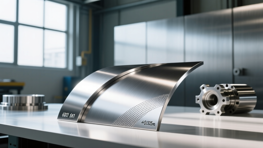
Standard CNC milling operations for commercial electronics housings typically hold tolerances of ±0.005" (0.127mm). However, safety and compliance standards demand significantly tighter control. For instance, an EMI shielding groove designed for a conductive elastomer gasket requires a depth tolerance of ±0.001" to ensure proper compression without over-stressing the gasket material, which would cause it to extrude and fail under thermal cycling.
As tolerances tighten, the cost of machining does not increase linearly; it scales exponentially due to reduced feed rates, mandatory secondary inspection (such as Coordinate Measuring Machine or CMM verification), and higher scrap rates.
| Enclosure Feature | Standard Tolerance | Compliance Tolerance | Cost Multiplier |
|---|---|---|---|
| General Pocketing | ±0.005" | N/A | 1.0x (Baseline) |
| EMI Gasket Grooves | ±0.005" | ±0.001" | 1.8x |
| IP67 O-Ring Glands | ±0.003" | ±0.001" (Depth/Width) | 2.2x |
| Mating Flange Faces | ±0.010" | ±0.0005" (Flatness) | 2.5x |
For a standard 6x4x2" 6061-T6 aluminum enclosure, baseline machining might cost $140–$180 per unit at mid-volume. Incorporating the tight tolerances required for full IP67 and MIL-STD-461 compliance pushes the machining cost to $350–$420 per unit before secondary finishing.
EMI/RFI Shielding: MIL-STD-461 and the Surface Finish Tax
Achieving electromagnetic compatibility (EMC) requires a continuous conductive path between the enclosure lid and the base. This is typically achieved using conductive gaskets, such as silver-aluminum filled silicones (e.g., Parker Chomerics CHO-SEAL). For these gaskets to function, the mating aluminum surfaces must remain electrically conductive.
This creates a major conflict with standard CNC finishing practices. Standard Type II or Type III (hard) anodizing creates an aluminum oxide layer that is highly non-conductive. To maintain conductivity, machine shops must either:
- Mask the gasket surfaces before anodizing, which adds 20-30% to the finishing labor cost.
- Apply a conductive chromate conversion coating (such as Alodine 1200s, which is RoHS compliant) instead of anodizing, sacrificing the cosmetic and wear-resistant benefits of anodize.
- Specify Electroless Nickel plating (per AMS2404), which provides excellent conductivity and corrosion resistance but costs 3x to 4x more than standard anodizing.
Furthermore, the surface finish of the EMI groove is critical. A surface that is too rough will cut into the soft conductive gasket during assembly, while a surface that is too smooth may not provide enough friction to seat the gasket properly. The industry standard specifies a maximum roughness of 63 µin Ra (1.6 µm) for EMI mating surfaces.
IP67 and IP68 Sealing: Navigating AS568 O-Ring Glands
When designing for water and dust ingress protection, engineers rely on the AS568 O-ring design standards to specify gland dimensions. The geometry of these glands frequently forces CNC operators into difficult machining scenarios.
"Static face seals require a surface finish between 16 and 32 µin Ra. If the CNC tool leaves chatter marks or directional lay lines perpendicular to the seal, micro-leaks will occur under hydrostatic pressure, regardless of how perfectly the gland depth is held."
The Undercut Problem: Internal face seals often require an undercut geometry to retain the O-ring during assembly. Standard flat-bottom end mills cannot machine undercuts. Shops must deploy specialized lollipop (undercut) end mills. These tools have a reduced neck diameter, making them highly susceptible to deflection and vibration. To prevent tool breakage and ensure the required ±0.001" tolerance, operators must drastically reduce feed rates and take shallow step-downs, significantly increasing cycle time and driving up cnc machining costs.
Material Selection for ATEX and Hazardous Locations
Enclosures destined for explosive environments (oil & gas, chemical processing) must comply with ATEX or IECEx directives, which mandate strict spark-resistance and impact-durability. While 6061-T6 aluminum is the default for commercial electronics, hazardous area enclosures frequently require 316L stainless steel or specialized bronze alloys to prevent galvanic sparking.
Machining 316L stainless steel introduces severe cost penalties compared to aluminum:
- Tool Wear: 316L work-hardens rapidly. It destroys standard carbide end mills up to 3x faster than 6061-T6, necessitating frequent tool changes and the use of premium AlTiN-coated tooling.
- Cycle Times: Due to the material's toughness and poor thermal conductivity, spindle speeds and feed rates must be reduced by 40-50% to prevent burning the cutting edges.
- Surface Finish Challenges: Achieving the 16 µin Ra required for O-ring sealing on 316L often requires a secondary manual polishing step, as CNC milling alone can leave microscopic tear-outs in the stainless grain structure.
For a comprehensive understanding of how these materials hold up under extreme environmental stress, testing protocols outlined in the MIL-STD-810 environmental engineering guidelines dictate that the enclosure must survive thermal shock and salt fog exposure without compromising the seal integrity.
Actionable DFM Framework to Control CNC Machining Costs
You do not have to sacrifice safety compliance to optimize your manufacturing budget. Implement the following DFM rules during the CAD phase to mitigate unnecessary cost escalations:
✅ 5 Rules for Cost-Effective Compliant Enclosures
- Standardize O-Ring Sizes: Design all glands around standard AS568 dash sizes (e.g., -214, -222). Custom metric O-rings require custom gland tooling and increase inspection complexity.
- Avoid Deep, Narrow EMI Grooves: If an EMI groove is deeper than 3x its width, standard end mills will chatter. Redesign the groove to be wider and shallower, utilizing a low-profile conductive gasket instead.
- Provide Tool Clearance for Lollipop Mills: If an undercut O-ring gland is mandatory, ensure the entry slot is at least 20% wider than the cutting diameter of the lollipop mill to allow for chip evacuation and tool deflection.
- Separate Cosmetic from Functional Surfaces: In your CAD model, explicitly color-code or note the EMI mating surfaces. This allows the machine shop to mask only the critical areas for anodizing, rather than masking the entire interior cavity.
- Design for CMM Accessibility: Tight tolerances require tight inspection. Ensure your CMM (Coordinate Measuring Machine) probe can physically reach the bottom of the O-ring gland without the probe shank rubbing against the sidewalls.
Certification Testing Failures: The Ultimate Cost Multiplier
The most expensive mistake in electronics enclosure manufacturing is discovering a compliance failure after the units have been machined, finished, and assembled. A common failure mode in IP68 testing is micro-leakage caused by galvanic corrosion between a stainless steel fastener and an aluminum enclosure body, which pits the aluminum sealing surface over time. To prevent this, specify isolated fastener holes or utilize A2-70 stainless steel hardware with nylon shoulder washers.
Another frequent failure occurs during MIL-STD-810H thermal cycling. If the CNC machined lid and base have mismatched wall thicknesses, they will expand and contract at different rates. This differential thermal expansion can break the EMI gasket seal at the corners, resulting in a failed EMC emissions test. Maintaining uniform wall thickness (ideally within 10% variance) across the entire CNC'd enclosure is a non-negotiable requirement for high-reliability safety applications.
Summary Matrix: Compliance Standard vs. Machining Requirement
| Standard | Primary Machining Impact | Critical Tolerance / Finish | Cost Driver |
|---|---|---|---|
| IP67 / IP68 | O-ring gland milling, undercutting | ±0.001" depth; 16-32 µin Ra | Specialized tooling, slow feeds |
| MIL-STD-461 | EMI groove milling, surface prep | ±0.001" width; 63 µin Ra max | Masking, conductive plating |
| ATEX / IECEx | Machining 316L SS or Bronze | Impact resistance, spark-free | 3x tool wear, 50% slower cycles |
| MIL-STD-810H | Uniform wall thickness, corner radii | ±0.005" wall uniformity | Multi-axis setups, CMM inspection |
By aligning your CAD designs with the physical realities of CNC toolpaths and metrology, you can achieve rigorous safety compliance without inflating your cnc machining costs beyond project viability. For further reading on standardizing CNC tolerances across your supply chain, consult the industry tolerance guidelines to ensure your engineering drawings communicate the exact intent required by the machine shop.