Surface Finish & Tolerances in Robotic CNC Machining Services
Explore how robotic CNC machining services achieve tight tolerances and superior surface finishes using active compliance and closed-loop laser tracking.
The Physics of Robotic Milling: Serial vs. Orthogonal Kinematics
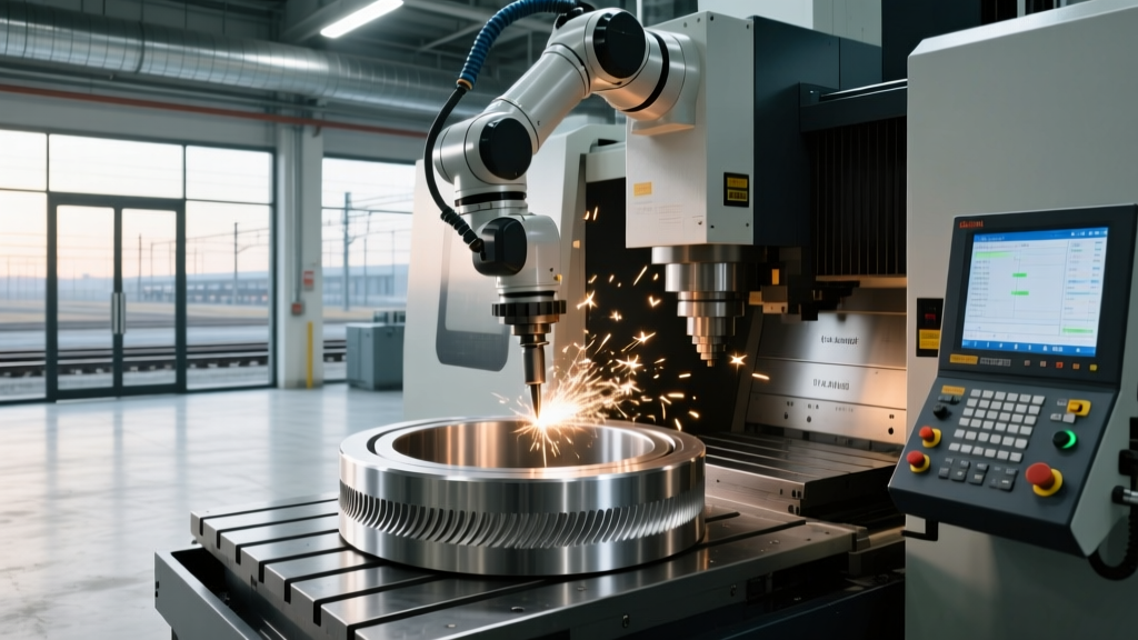
To understand tolerance capabilities in robotic CNC machining services, engineers must first contrast serial kinematics (robotic arms) with orthogonal kinematics (traditional 3-axis or 5-axis CNC beds). A standard vertical machining center (VMC) relies on massive cast-iron beds and linear guideways, offering structural stiffness typically exceeding 50 N/µm. In contrast, a 6-axis robot like the FANUC M-900iB/280 utilizes a chain of rotary joints and harmonic drives.
This serial linkage creates a compounding stiffness issue. When a 12kW HSD ES929 spindle (running at 24,000 RPM) engages with 6061-T6 aluminum at a depth of cut (DOC) of 5mm, the cutting forces induce micro-deflections in the robot's wrist joints. Without compensation, this deflection translates directly into toolpath deviation, resulting in poor surface finishes characterized by severe chatter marks and dimensional inaccuracies exceeding ±0.15mm.
Decoding Tolerance Standards: ISO 230-2 and Closed-Loop Compensation
When evaluating a contract machining partner, native robot repeatability is a misleading metric. A high-payload robotic arm may boast a repeatability of ±0.03mm, but its absolute volumetric accuracy can drift by over 0.5mm across a 3-meter work envelope due to thermal expansion in the joint reducers and gear backlash.
Leading robotic CNC machining services now rely on ISO 230-2:2014 Test code for machine tools to certify positioning accuracy. To meet the strict ±0.05mm tolerance bands required for aerospace structural components, shops deploy closed-loop laser tracking systems. Devices like the API Radian or Leica AT960 laser trackers monitor the spindle's tool center point (TCP) in real-time at 1,000 Hz. If thermal drift causes the Z-axis to sag by 0.04mm during a 90-minute roughing cycle, the laser tracker feeds this deviation back to the robot controller, dynamically adjusting the joint angles to maintain absolute positional accuracy.
⚠️ The Thermal Drift Edge Case: Harmonic drives in the robot's J3 and J4 joints generate significant heat during continuous high-speed milling. After 45 minutes of operation, thermal expansion can shift the TCP by up to 0.12mm. Specify that your machining partner utilizes active liquid-cooling jackets on the primary joint reducers and performs a 15-minute thermal warm-up cycle before cutting critical tolerance features.Surface Finish Metrics: Achieving Ra 0.8 µm on Flexible Arms
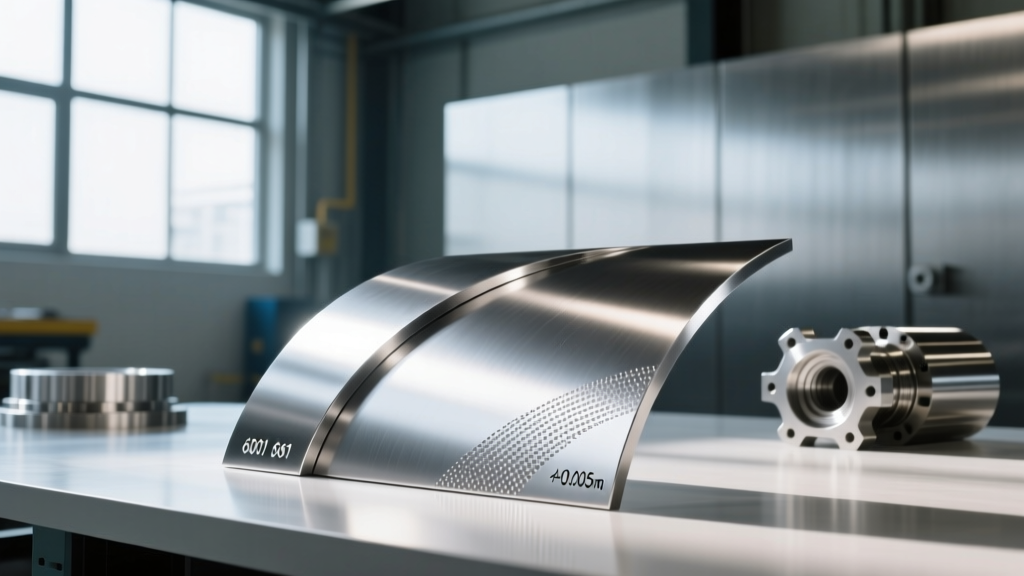
Surface roughness in robotic milling is governed by the ISO 1302 Geometrical Product Specifications standard. Achieving a fine surface finish (Ra 0.8 µm or 32 µin) on a flexible robotic arm requires suppressing regenerative chatter, which is the primary enemy of surface integrity in serial kinematic systems.
Toolpath and Tooling Strategies for Chatter Suppression
- Trochoidal Milling: Maintaining a constant radial engagement (typically 5% to 10% of the tool diameter) prevents sudden spikes in cutting forces that cause joint deflection.
- Variable Pitch End Mills: Using tooling like the Sandvik Coromant CoroMill 390 with uneven flute spacing disrupts the harmonic frequencies that trigger robotic arm resonance.
- Spindle Speed Optimization: Utilizing tap-testing and stability lobe diagrams to identify the exact 'sweet spot' RPM (often between 18,000 and 22,000 RPM for carbide tooling in aluminum) where the robot's natural frequency does not amplify cutting vibrations.
Active Force Control: The Secret to Consistent Ra Values
The most significant innovation in modern robotic CNC machining services is the integration of active compliance. Unlike a rigid CNC machine that blindly follows a programmed G-code path regardless of part warpage or fixture variation, advanced robotic cells utilize 6-axis force/torque sensors (such as the ATI Industrial Automation Gamma series) mounted between the robot wrist and the spindle.
This sensor allows the robot to 'feel' the cutting forces. If the tool encounters a hard spot in a titanium forging or a slight warp in a composite layup, the force sensor detects the spike in normal force and commands the robot to instantaneously retract the tool by 0.05mm. This active compliance prevents tool breakage, eliminates gouging, and ensures a uniform surface finish (Rz) across large, non-planar surfaces like wind turbine blade molds or aircraft wing skins.
Comparative Matrix: 5-Axis CNC vs. Robotic CNC Services
| Specification | Traditional 5-Axis VMC | 6-Axis Robotic CNC (Compensated) |
|---|---|---|
| Work Envelope | Typically < 3m x 2m x 1m | Up to 10m+ via linear tracks & gantries |
| Absolute Accuracy | ±0.005mm to ±0.015mm | ±0.03mm to ±0.05mm (with laser tracking) |
| Surface Finish (Al 6061) | Ra 0.4 µm (Mirror finish capable) | Ra 0.8 µm to 1.6 µm (Standard milled) |
| Material Hardness Limit | Hardened steels up to 65 HRC | Best for Al, Plastics, Composites, Wood |
| Capital & Hourly Cost | $150 - $300+ / hour | $80 - $140 / hour |
Buyer’s Specification Matrix for 2026 Contracts
When sourcing robotic CNC machining services for large-format or complex geometry parts, generic RFQs lead to catastrophic tolerance failures. Use the following technical checklist to qualify your machine shop's robotic capabilities:
- Kinematic Calibration Protocol: Require proof of annual volumetric error mapping using a laser tracker or ballbar system, conforming to ISO 230-2.
- Spindle Runout Certification: High-speed robotic spindles must be dynamically balanced to ISO 1940 G0.4 standards. Demand a runout certificate showing < 0.003mm TIR at the toolholder nose.
- Fixturing Rigidity: Because the robot arm will yield before the fixture does, the shop must utilize vacuum chucks with high-friction elastomer pads or multi-point hydraulic clamping to prevent part movement under lateral cutting loads.
- Post-Processor Validation: Ensure the shop uses advanced CAM post-processors (like HyperMill or Mastercam Robot) that specifically account for the robot's singularity zones and joint limits, preventing mid-cut axis flips that ruin surface finishes.
Industry Insight: According to data from the National Institute of Standards and Technology (NIST) Robotics Division, the integration of AI-driven adaptive control in robotic machining has reduced scrap rates in aerospace composite trimming by over 40% since 2024. By monitoring spindle load and acoustic emissions in real-time, modern robotic cells can adjust feed rates on the fly to maintain constant chip thickness, directly optimizing the Ra surface finish metric.
Final Engineering Verdict
Robotic CNC machining services are not a direct replacement for 5-axis VMCs when machining hardened steel to aerospace micron-level tolerances. However, for large-envelope applications involving aluminum, advanced polymers, carbon fiber composites, and wood, the modern compensated robotic arm offers an unbeatable combination of geometric flexibility, rapid material removal, and highly consistent surface finishes. By mandating closed-loop laser tracking, active force compliance, and strict adherence to ISO metrology standards in your procurement contracts, you can reliably achieve Ra 0.8 µm finishes and ±0.05mm tolerances at a fraction of traditional CNC costs.