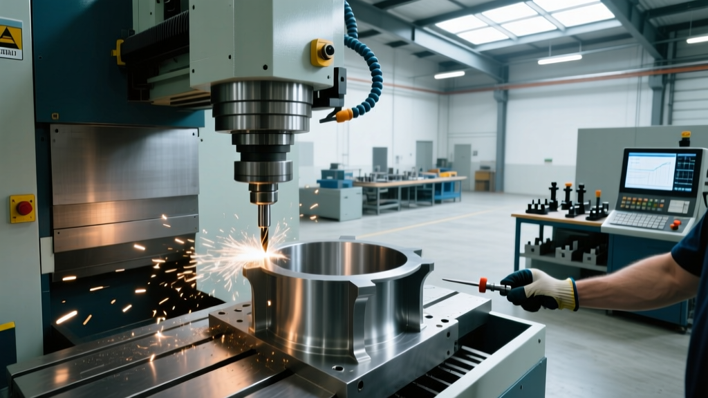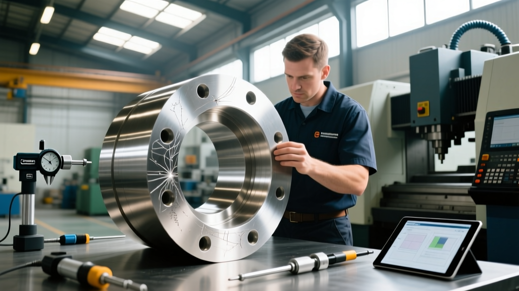
Tolerance & Finish Troubleshooting at a Large CNC Machining Company
Diagnose and resolve CNC surface finish and GD&T tolerance failures. Expert troubleshooting matrix for large CNC machining company operations.
The Hidden Cost of Out-of-Tolerance Parts in High-Volume Production
When managing spindle fleets across a multi-shift operation, a single out-of-tolerance drift can yield thousands of dollars in scrap before the next CMM (Coordinate Measuring Machine) audit catches it. For a large CNC machining company, surface finish degradation and geometric tolerance failures are rarely isolated incidents; they are systemic symptoms of thermal, harmonic, or metrological breakdowns. Diagnosing these issues requires moving beyond basic feed-and-speed adjustments and into the physics of tool deflection, harmonic resonance, and thermal growth.
CRITICAL ALERT: Never adjust cutter compensation (G41/G42) to fix a surface finish issue without first verifying toolholder runout. Masking a harmonic chatter problem with offset tweaks will inevitably lead to catastrophic tool failure and scrapped raw material on the next setup.Diagnostic Matrix: Surface Finish (Ra/Rz) vs. Dimensional Tolerance Failures
The following troubleshooting matrix isolates the most common failure modes encountered in high-production CNC milling and turning environments. Use this as a primary decision tree on the shop floor.
| Defect Signature | Metrology Reading | Root Cause Analysis | Immediate Machine-Side Corrective Action |
|---|---|---|---|
| Chatter Marks / Regenerative Vibration | Ra > 125 µin, visible harmonic waves | Spindle RPM matches natural frequency of tool-workpiece system | Adjust RPM by ±15% to hit a stable lobe; increase radial depth of cut (RDOC) to dampen vibration. |
| Bore Taper / Out-of-Roundness | Cylindricity > 0.0008", taper at Z-depth | Tool deflection due to L:D (Length-to-Diameter) ratio exceeding 4:1 | Switch to solid carbide shank or install a tuned-mass-damper anti-vibration boring bar. |
| Flatness Drift on Milled Faces | Flatness > 0.0015" across 12" part | Thermal growth in machine trunnion or spindle Z-axis expansion | Implement a mandatory 15-minute spindle/table warmup macro at 8,000 RPM before first-article probing. |
| Poor Thread Surface Finish / Galling | Ra > 63 µin, visible Built-Up Edge (BUE) | Cutting speed too low for workpiece material; inadequate chip evacuation | Increase surface speed (SFM) by 20%; activate through-tool coolant at minimum 1,000 PSI. |
| True Position Shift in Bolt Patterns | Position > 0.005" from datum | Workholding distortion or sequential clamping stress release | Reduce hydraulic clamping pressure by 20%; re-sequence toolpaths to rough all holes before finishing. |
Step-by-Step Troubleshooting: Harmonic Instability and Tool Deflection
Surface finish failures in deep-cavity milling or long-reach turning are almost always rooted in harmonic instability. When a large CNC machining company tackles aerospace structural components or deep-bore hydraulic manifolds, standard tooling fails due to the physics of cantilever beam deflection.
1. Harmonic Frequency Analysis and Stability Lobes
Chatter occurs when the frequency of tooth impacts aligns with the natural resonant frequency of the tool or workpiece. To resolve this, machinists must utilize Stability Lobe Diagrams (SLDs). If your facility lacks tap-testing equipment (such as a Machining Dynamics MLI system), apply the empirical rule of thumb for chatter mitigation:
- Speed Variation: Change the spindle RPM by 10% to 20%. If chatter worsens, reverse the direction of the RPM change. You are searching for the 'sweet spot' between harmonic peaks.
- Radial Engagement: Counterintuitively, increasing the radial depth of cut (stepover) from 5% to 15% of the cutter diameter can sometimes stabilize the cut by altering the cutting force vector and damping the vibration.
- Variable Helix/Pitch Cutters: Replace standard end mills with variable helix geometry tools (e.g., Kennametal HARVI or Harvey Tool variable helix lines). The unequal spacing of the flutes disrupts the regenerative chatter frequency.
2. Toolholder Runout Verification
Total Indicated Runout (TIR) at the tool tip directly dictates both surface finish and tool life. A runout of just 0.0004" can cause one flute of a 4-flute end mill to do 80% of the work, destroying the surface finish and throwing dimensional tolerances out of spec due to uneven tool wear.
Toolholder TIR Comparison at 3x Diameter Extension
- ER32 Collet Chuck: ~0.0002" - 0.0005" TIR (Acceptable for roughing, poor for finishing Ra < 32 µin)
- Shrink-Fit Holder: ~0.0001" TIR (Excellent rigidity, requires induction heating unit)
- Hydraulic Chuck: ~0.00004" - 0.0001" TIR (Mandatory for high-speed finishing and reaming operations)
- Milling Chuck (e.g., BIG KAISER MEGA): ~0.0001" TIR (Best balance of rigidity and runout for heavy side-milling)
GD&T Troubleshooting: True Position and Flatness Drift
Geometric Dimensioning and Tolerancing (GD&T) failures often masquerade as tooling issues when they are actually thermal or workholding problems. According to the ASME Y14.5-2018 standard, geometric tolerances apply to the part in its free state unless otherwise specified. Clamping forces that distort a part during machining will result in a part that measures out-of-tolerance the moment it is removed from the vise.
"If your CMM shows a flatness error of 0.002" on a milled aluminum plate, but the surface finish is a perfect 16 Ra, your toolpath is fine. Your workholding is bending the part during the clamp cycle. Switch to low-profile toe clamps or use a vacuum chuck to eliminate Z-axis distortion."
Thermal Growth Compensation in 5-Axis Machining
In 5-axis simultaneous milling, the trunnion table and rotary axes generate significant heat from the torque motors. A temperature rise of just 15°C in the cast iron table can cause a Z-axis thermal shift of 0.001" to 0.003" over an 8-hour shift. To troubleshoot true position drift that worsens as the shift progresses:
- Verify the machine's thermal compensation sensors are clean and actively reading ambient and spindle temperatures.
- Implement a continuous coolant flow over the trunnion housing, even when the machine is in a tool-change state.
- Schedule mid-shift CMM audits. If the Z-depth is creeping shallow by 0.0005" every two hours, program a macro to automatically adjust the Z-work offset based on the machine's internal thermal probe data.
Advanced Coolant Interventions for Surface Finish
Flooding a part with standard 150 PSI coolant is insufficient for modern high-performance machining, particularly when cutting sticky alloys like Inconel 718 or 316L Stainless Steel. Built-Up Edge (BUE) on the cutting tool will tear the workpiece surface, resulting in an Ra finish that fails inspection.
- Through-Tool Coolant Pressure: Upgrade to a high-pressure coolant unit capable of 1,500 to 2,000 PSI. This pressure is required to penetrate the vapor barrier that forms at the cutting edge at high surface speeds, ensuring lubrication and breaking the chip.
- Coolant Concentration: Maintain a strict 8% to 10% concentration of semi-synthetic coolant using a digital refractometer. Dropping below 6% concentration reduces the lubricity film strength, leading to micro-welding and poor surface finishes.
- Chip Evacuation: In deep pocket milling, recut chips are the number one cause of localized surface finish failure and premature tool breakage. Use air-blast through the spindle (M-code M10/M11) during non-cutting rapid moves to clear the cavity.
Standard Compliance: Transitioning to ISO 21920
Quality control departments must be aware of the global shift in surface texture documentation. The legacy ISO 1302 standard has been officially replaced by the ISO 21920-1:2021 series. This new standard fundamentally changes how surface finish is specified on engineering drawings, moving away from simple Ra callouts to more comprehensive profile and areal parameters (such as Sa and Sz) that better reflect actual functional performance.
For a large CNC machining company, updating CMM software and profilometer firmware to interpret ISO 21920 syntax is mandatory to avoid rejecting good parts or accepting bad ones due to metrology miscommunication. Furthermore, relying on the NIST Engineering Laboratory guidelines for calibration ensures that your shop's measurement uncertainty remains within the acceptable 10:1 ratio relative to the part's geometric tolerance.
Final Diagnostic Checklist
Before scrapping a batch of parts or tearing down a machine spindle, run this 4-point verification checklist:
- Verify the Metrology: Is the CMM probe calibrated with the correct ruby stylus diameter? Is the sweep speed too fast, causing dynamic lobing errors?
- Audit the Toolholder: Pull the tool and measure TIR at the flutes. Clean the spindle taper with a specialized taper cleaning stick to remove microscopic coolant residue.
- Check the Workholding: Torque the vise or hydraulic clamps to the exact specification. Over-torquing causes elastic deformation that ruins true position and flatness.
- Review the CAM Strategy: Ensure the finishing toolpath utilizes climb milling exclusively, with a consistent chip thinning calculation applied to the feed-per-tooth.