What CNC Machining Photos Reveal About Aftermarket Safety Compliance
Learn how to audit CNC machining photos to verify safety compliance, material traceability, and SAE standards for automotive aftermarket parts.
When sourcing critical automotive aftermarket components—such as billet 6061-T6 aluminum suspension control arms, 4130 chromoly steering knuckles, or turbocharger T4 flanges—procurement teams face immense liability risks. In 2026, with global supply chains increasingly decentralized and performance vehicle tolerances tighter than ever, analyzing cnc machining photos is no longer just about admiring cosmetic surface finishes. It has become a critical first-line audit mechanism for verifying safety compliance, material traceability, and adherence to rigorous automotive standards.
⚠️ The Visual Compliance Blindspot: A highly polished part photo hides internal stresses, micro-fractures, and improper toolpaths. To truly vet a machine shop's adherence to safety standards, procurement engineers must demand photos of the raw material tags, in-process fixturing, and CMM (Coordinate Measuring Machine) setups alongside the finished component.Decoding Material Traceability in Shop Floor Photography
The foundation of automotive aftermarket safety is material integrity. Suspension and steering components are subject to extreme cyclic loading. A common and dangerous mistake in the aftermarket industry is the unauthorized substitution of 7075-T6 aluminum for 6061-T6. While 7075 boasts a higher yield strength (73 ksi vs. 40 ksi), it is highly susceptible to stress corrosion cracking (SCC) when exposed to road salts and moisture in unsprung suspension environments. SAE International standards strictly govern these material applications, and non-compliance can lead to catastrophic on-track or street failures.
When reviewing cnc machining photos provided by a prospective vendor, look past the shiny finished part and examine the background and raw stock. A compliant, ISO 9001-certified machine shop will naturally include the following in their visual documentation:
- Heat Lot Numbers: Visible stamps or laser etchings on the raw billet that match the Material Test Report (MTR).
- MTR Documentation: Photos showing the physical MTR resting on the shop bench next to the raw extrusion or forging before machining begins.
- Material Color Coding: Many top-tier shops use industry-standard color-coded end caps on raw bar stock (e.g., specific colors for 4130 chromoly vs. 1018 mild steel) to prevent bin-mixing. Spotting these in raw setup photos confirms rigorous inventory control.
Fixturing and Tooling Red Flags: Avoiding Stress Concentrators
Improper CNC fixturing and toolpath generation are primary culprits behind aftermarket part failures. Billet aluminum intake manifolds and turbo flanges require strict flatness tolerances (often within 0.002 inches across the mating surface) to prevent exhaust leaks or vacuum loss. If a shop uses excessive clamping force with standard step clamps, the part will distort during machining and spring back out of tolerance once unclamped.
Furthermore, sharp internal corners left by standard endmills create severe stress risers in structural components like steering knuckles. Compliant shops use undercut endmills (lollipop cutters) to machine internal radii, dispersing mechanical stress. The following table outlines what specific visual cues in machining photos reveal about a shop's engineering competence:
| Visual Cue in Photo | Compliance Implication | Risk Level |
|---|---|---|
| Custom machined aluminum soft jaws | Indicates dedicated fixturing to prevent part distortion and marring on finished cosmetic surfaces. | Low |
| Standard step clamps on thin walls | High risk of clamping distortion; part will fail flatness tolerances upon release. | High |
| Sharp 90-degree internal pockets | Toolpath limitation; creates a massive stress concentrator leading to fatigue cracking under load. | Critical |
| Vacuum workholding or magnetic chucks | Shows advanced investment in uniform clamping pressure for ultra-flat tolerance requirements. | Low |
Metrology and CMM Verification: Proving the Tolerances
In the automotive aftermarket, claiming a tolerance of ±0.0005 inches for a wheel hub bearing bore is meaningless without the metrology to prove it. In 2026, coordinate measuring machines (CMM) from manufacturers like Zeiss and Hexagon are the industry standard for verifying complex geometries. However, CMM programming is expensive, typically costing $95 to $140 per hour, with batch inspection running around $55 per hour.
Because of this cost, lower-tier machine shops will skip CMM inspection and rely on manual calipers or micrometers, which cannot accurately measure true position or complex profile tolerances. When auditing cnc machining photos, actively search for the following metrology evidence:
- The CMM Setup: Look for the part mounted on a granite surface plate with a Renishaw or Zeiss touch probe hovering over a critical feature.
- Optical Comparators: For small, complex aftermarket parts like fuel injector bungs or turbo V-band flanges, an optical comparator photo proves the shop is verifying thread pitch and angle geometries.
- Surface Profilometers: Aftermarket fuel rails and oil pump housings require specific surface finishes for O-ring sealing (typically Ra 32 µin or 0.8 µm). A photo showing a surface roughness tester on the mating face confirms the shop monitors tool wear and feed rates to maintain sealing integrity.
Navigating SAE, DOT, and SEMA Compliance Standards
The automotive aftermarket is not the wild west; it is heavily regulated. Components that affect vehicle dynamics, braking, or emissions must comply with specific regulatory frameworks. The Federal Motor Vehicle Safety Standards (FMVSS) dictate rigorous testing for steering and suspension components. If a CNC shop machines a steering arm with an unverified alloy or improper heat treatment, the brand selling that part assumes full liability in the event of an accident.
'In the current liability landscape, a brand cannot use the defense that their machine shop deviated from the CAD model. If the part fails, the brand is liable. Visual audits of the machining process are your only shield against rogue shop floor practices.' — Automotive Aftermarket Liability Consultant, 2026 Industry Report
Furthermore, organizations like the SEMA Garage provide vital resources for aftermarket companies to test and verify compliance with OEM and regulatory standards. A machine shop that understands SEMA compliance will proactively provide photos of their first-article inspection (FAI) processes, proving they are not just making parts that 'look right,' but parts that measure exactly to the engineered safety margins.
The Auditor’s Photo Checklist for Aftermarket Procurement
To effectively vet a CNC machining partner for safety-critical automotive components, mandate a visual documentation package that includes the following specific shots before signing any production contract:
✅ Mandatory Visual Audit Checklist
- Raw Material Tag: Clear photo of the mill certification tag attached to the raw billet/bar stock.
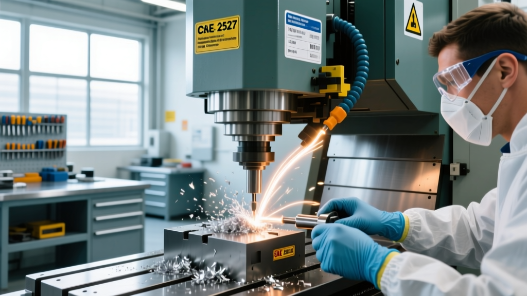
- In-Process Fixturing: Photo of the part clamped in the CNC vise or tombstone, showing jaw contact points and clamp pressure distribution.
- Toolpath Simulation: Screenshot from the shop's CAM software (e.g., Mastercam, Fusion 360) showing tool engagement and internal corner radii strategies.
- Deburring Station: Photo of the manual or thermal deburring setup. Improper deburring leaves micro-burrs that can break off and destroy engine bearings or hydraulic valves.
- First Article CMM Report: Photo of the physical part on the CMM bed alongside the printed, color-coded deviation map.
By shifting the focus from aesthetic part photography to rigorous process documentation, procurement engineers can drastically reduce the risk of field failures. The right cnc machining photos tell a comprehensive story of metallurgical discipline, metrological precision, and an unwavering commitment to automotive safety standards.