What Is G-Code in CNC Machine Programming vs Alternatives
Understand what is G-code in CNC machine programming and compare it against Conversational controls and CAM software to optimize shop floor workflows.
The Baseline: What Is G-Code in CNC Machine Operations?
At its core, G-code (Geometric Code) is the foundational alphanumeric programming language that directs the physical movements and auxiliary functions of CNC (Computer Numerical Control) equipment. Originally standardized under the RS-274 specification by the Electronic Industries Alliance (EIA) and later maintained by NIST, G-code serves as the universal translator between digital design intent and physical machining kinematics.
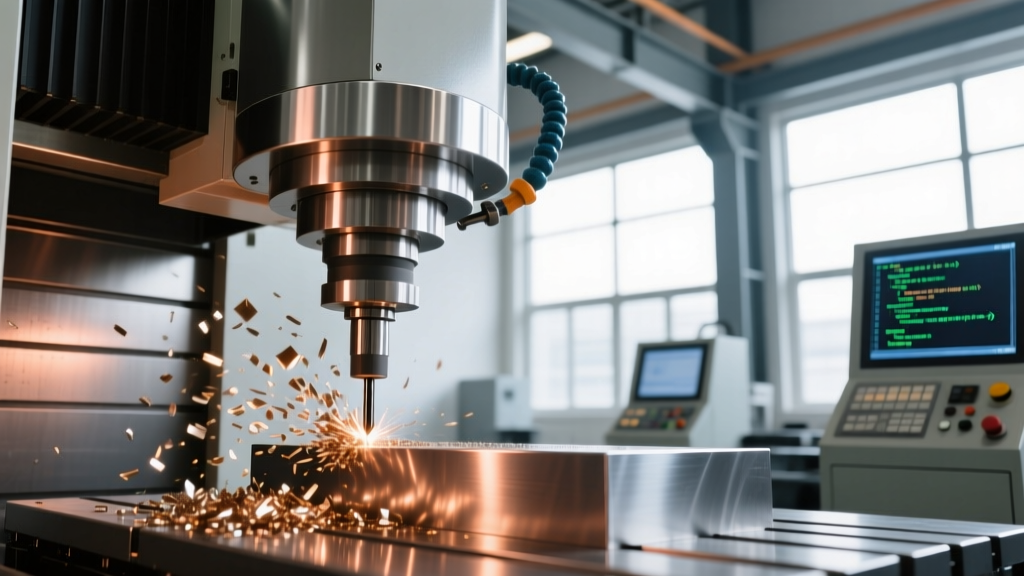
When a machinist or programmer asks, 'what is G-code in CNC machine environments,' the technical answer is that it is a sequential instruction set composed of preparatory functions (G-codes) and miscellaneous functions (M-codes). For example, on a standard Fanuc 31i-B5 or Haas Next Generation Control (NGC), a G01 command dictates linear interpolation at a specified feed rate (F), while an M08 command triggers the coolant pump.
Core G-Code Modal Groups (Fanuc/Haas Standard):- Group 01 (Motion): G00 (Rapid), G01 (Linear), G02/G03 (Circular Interpolation)
- Group 02 (Plane Selection): G17 (XY), G18 (ZX), G19 (YZ)
- Group 06 (Units): G20 (Inch), G21 (Metric)
- Group 09 (Canned Cycles): G81 (Simple Drill), G83 (Peck Drill), G84 (Rigid Tap)
While manual G-code programming remains a critical skill for shop-floor troubleshooting and quick edits, modern manufacturing requires evaluating it against advanced alternatives like Conversational Programming and Computer-Aided Manufacturing (CAM) software. The choice between these methods directly impacts cycle times, setup costs, and scrap rates.
Comparative Matrix: G-Code vs. Conversational vs. CAM
To determine the optimal programming workflow for your facility, we must compare manual G-code against proprietary conversational interfaces (like Mazak Mazatrol or Haas IPS) and offline CAM systems (like Mastercam 2026 or Autodesk Fusion).
| Feature | Manual G-Code (RS-274) | Conversational (Mazatrol / Haas IPS) | Offline CAM (Mastercam / Fusion) |
|---|---|---|---|
| Setup Time (Prismatic) | Fast (10-15 mins) | Very Fast (5-10 mins) | Slow (30-60+ mins) |
| Complex 3D Contouring | Nearly Impossible | Limited (2.5D to simple 3D) | Excellent (5-Axis Simultaneous) |
| Machine Editing | High (Direct text edit) | High (Visual GUI edit) | Low (Requires reposting) |
| Learning Curve | Steep (40-80 hrs training) | Moderate (15-20 hrs) | Steep (100+ hrs for 5-axis) |
| Estimated Software Cost | $0 (Included in control) | $0 - $2,500 (Option dependent) | $3,000 - $12,000+ per seat |
Deep Dive: Conversational Programming as the Shop-Floor Alternative
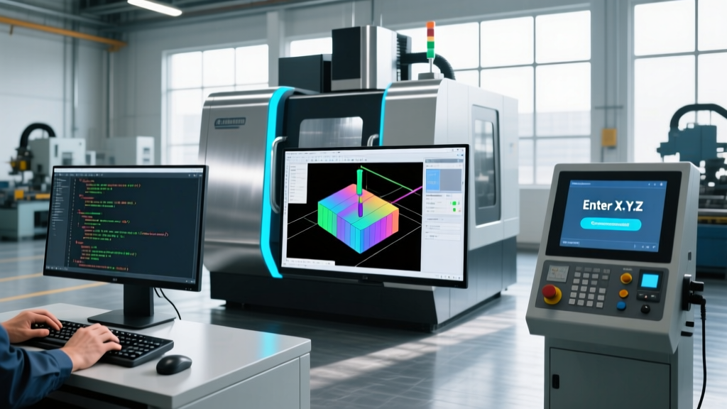
Conversational programming was developed specifically to bypass the verbosity and syntax-strictness of raw G-code. Systems like the Haas Intuitive Programming System (IPS) or Mazak's SmoothG Mazatrol allow operators to input part geometry using visual prompts rather than memorizing coordinate geometry and trigonometry.
Where Conversational Wins
For high-mix, low-volume job shops producing 2.5D prismatic parts (brackets, flanges, simple enclosures), conversational programming reduces setup time by up to 60% compared to offline CAM. An operator can measure a raw casting, input the stock dimensions into the Mazatrol interface, define a pocket with a simple corner-radius prompt, and the control automatically calculates the toolpath, including approach vectors and retract heights.
Where Conversational Fails
Conversational controls lack the computational engine required for complex surface finishing or 5-axis simultaneous machining. If you are machining a titanium impeller with blended fillets or an aerospace turbine blade requiring continuous tool-axis vector tilting to avoid singularities, conversational interfaces are entirely inadequate. Furthermore, conversational programs are largely locked to their native controller ecosystem; a Mazatrol file cannot be natively transferred to a Fanuc-controlled Okuma or DMG Mori machine without specialized third-party translation software.
Critical Warning: Cutter Compensation (G41/G42) in Manual G-CodeWhen manually programming G-code, improper use of G41 (Left Comp) and G42 (Right Comp) is the leading cause of $15,000+ spindle crashes. The control requires a linear lead-in move (G01 or G00) that is strictly longer than the cutter radius to establish the offset vector. Attempting to engage cutter compensation on a G02/G03 arc or a line shorter than the tool radius will trigger a P/S alarm (typically Alarm 034 or 035 on Fanuc) or result in severe gouging if the control's look-ahead fails to catch the interference.
The CAM Paradigm: Offline Toolpath Generation
Modern CAM software like Mastercam, Siemens NX, and Autodesk Fusion operates on a fundamentally different premise. Instead of writing G-code directly, the programmer generates toolpaths based on 3D CAD boundary conditions. The CAM system calculates the cutter location (CL) data, which is then passed through a Post-Processor to translate the generic CL-data into machine-specific G-code.
The Hidden Costs and Risks of CAM
While CAM is mandatory for complex geometries, it introduces the 'Post-Processor Bottleneck.' A post-processor is a custom script that formats the CL-data for a specific machine's kinematics and control dialect. If a shop purchases a new 5-axis trunnion table machine but uses an outdated or generic post-processor, the generated G-code may output incorrect rotary axis vectors (e.g., outputting B-axis commands instead of A-axis), leading to immediate catastrophic collisions.
Furthermore, editing CAM-generated G-code at the machine is highly discouraged. Because CAM relies on thousands of lines of microscopic linearization (G01 moves) to approximate arcs and splines, manually altering a coordinate in the middle of a CAM program breaks the continuous surface finish and can create dwell marks or gouges. According to Sandvik Coromant's milling expertise guidelines, maintaining consistent chip thickness and tool engagement requires the precise, unbroken toolpaths that only verified CAM outputs can provide for 3D surfacing.
Decision Framework: Choosing Your Programming Method
Shop managers and lead programmers should apply the following decision matrix to assign the correct programming workflow to incoming jobs:
- Is the part a simple 2D/2.5D geometry (pockets, holes, facing) with a setup time under 20 minutes?
- Yes: Use Conversational Programming at the machine. It eliminates CAM overhead and allows instant spindle-on time.
- Does the job require mid-cycle probing, custom macro logic, or specialized canned cycles (e.g., G83 peck drilling with specific chip-breaking retracts)?
- Yes: Use Manual G-Code. Conversational interfaces often restrict access to deep macro variables (#100-#199) and custom probing routines (G65 P9810).
- Does the part feature complex 3D surfacing, 5-axis simultaneous movement, or require multi-axis toolpath optimization for cycle time reduction?
- Yes: Use Offline CAM. Ensure the post-processor is verified using CNC simulation software (like Vericut or NCSIMUL) before sending the G-code to the shop floor.
Summary: The Symbiotic Shop Floor
Understanding what is G-code in CNC machine operations is not about choosing it exclusively over modern alternatives, but recognizing it as the underlying bedrock of all CNC motion. Even the most advanced CAM software and conversational interfaces ultimately compile down to G-code and M-code at the control level. The most profitable machine shops in 2026 do not rely on a single method; they equip their operators with conversational tools for rapid prototyping, invest in high-end CAM for complex aerospace and medical components, and maintain deep manual G-code expertise to troubleshoot, optimize, and verify the final output at the spindle.