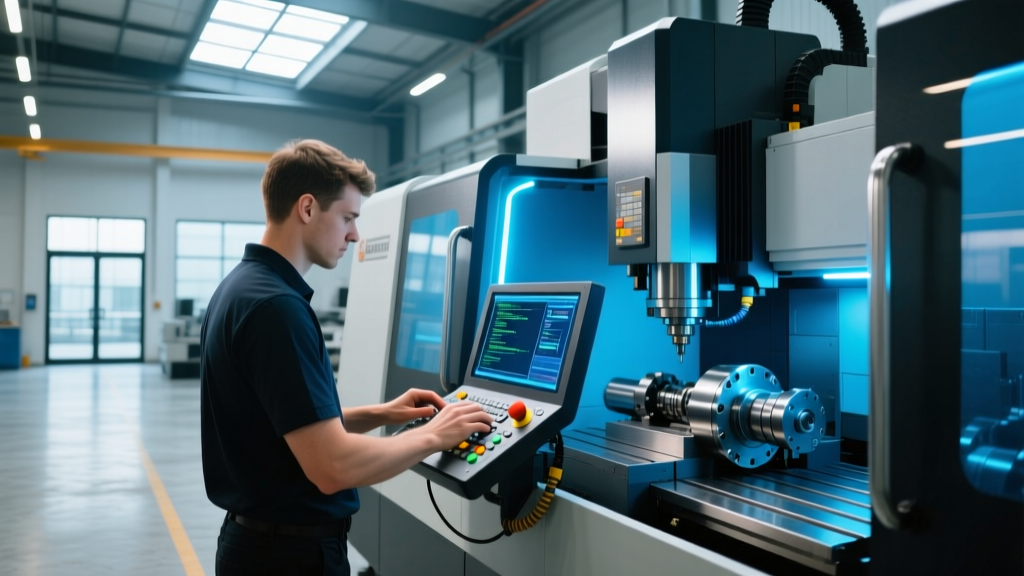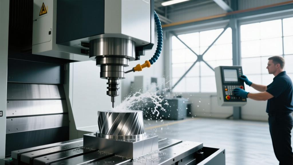
CNC Machining Processes: A Guide to Machine Tools and Programming
Explore real-world CNC machining processes, machine tools, and programming strategies through aerospace and medical industry case studies and ROI data.
Core CNC Machining Processes in High-Mix Manufacturing
Translating complex CAD geometries into physical components requires a precise alignment of machine kinematics, cutting tool physics, and CAM software logic. In high-mix, low-volume environments like aerospace and medical device manufacturing, standard 3-axis milling is rarely sufficient. Advanced CNC machining processes rely on simultaneous multi-axis interpolation and mill-turn capabilities to maintain tight geometric tolerances (often within ±0.005 mm) while minimizing setup-induced errors.
According to advanced manufacturing research from the National Institute of Standards and Technology (NIST), the integration of 5-axis kinematics with adaptive toolpath generation reduces cumulative setup times by up to 45% compared to indexed 3+2 axis machining. This efficiency is critical when machining high-strength, low-machinability alloys like Inconel 718 or Ti-6Al-4V.
| Process Type | Machine Configuration | Primary Application | Typical CAM Strategy | Cost Range (USD) |
|---|---|---|---|---|
| 3-Axis Milling | Vertical Machining Center (VMC) | Prismatic parts, brackets, molds | Adaptive Clearing, Contouring | $80,000 - $150,000 |
| 4-Axis Indexing | VMC + Rotary Table | Cylindrical parts, camshafts | Rotary Roughing, Wrap Toolpaths | $120,000 - $220,000 |
| 5-Axis Simultaneous | Trunnion or Swivel Head | Blisks, impellers, structural aero | Swarf Machining, Flowline | $350,000 - $800,000+ |
| Mill-Turn (B-Axis) | Horizontal/Vertical Turn-Mill | Medical implants, hydraulic valves | Turn-Profile, C/Y-Axis Milling | $400,000 - $950,000+ |
Machine Tool Selection: Real-World Case Studies
Selecting the correct machine tool is not merely about workspace volume; it involves evaluating spindle torque curves, thermal stability, and CNC controller look-ahead capabilities. Below are two industry case studies demonstrating how specific machine and programming combinations solve distinct manufacturing bottlenecks.
Case Study 1: Aerospace Titanium Blisk Machining
The Challenge: A Tier-2 aerospace supplier needed to machine a compressor blisk (bladed disk) from a solid billet of Ti-6Al-4V. The previous 3+2 axis process required 42 hours per part, with excessive tool wear due to constant engagement angles and deep cavity chatter.
The Solution: The facility upgraded to a DMG Mori DMU 80 P duoBLOCK equipped with a 15,000 RPM spindle and a Siemens Sinumerik 840D sl controller. The programming team utilized Siemens NX CAM to generate 5-axis simultaneous trochoidal toolpaths.
- Tooling: Kennametal HARVI III 4-flute solid carbide end mills with AlTiN coating.
- Parameters: Spindle speed limited to 2,800 RPM to avoid harmonic resonance in the titanium billet. Axial depth of cut (ap) set to 1.5x tool diameter (18mm for a 12mm tool), with a radial stepover (ae) restricted to 6% of the diameter.
- Coolant: 70-bar through-tool high-pressure coolant to break stringy titanium chips.
Case Study 2: Medical Implant Mill-Turn Operations
The Challenge: Machining porous-coated titanium spinal cages required complex internal geometries and strict surface integrity. Secondary operations for deburring and cross-drilling were causing a 12% scrap rate due to handling damage.
The Solution: Implementation of a Willemin-Macodel 508MT 5-axis mill-turn center. The programming was handled via Mastercam 2026, utilizing the Machine Simulation module to verify clearance in the tight B-axis machining envelope.
By utilizing the machine's B-axis milling head, the shop performed turning, 5-axis contouring, and cross-drilling in a single chucking. The G-code was optimized using G187 (Haas equivalent) or Siemens G64 (Continuous Path Mode) to blend sharp vector transitions into smooth arcs, eliminating microscopic dwell marks that could harbor bacteria in the final implant.
Programming Strategies: From CAM to G-Code Optimization
Generating a toolpath in CAM software is only the first step. The post-processor must translate these vectors into machine-specific G-code that respects the physical limits of the CNC controller. Industry data compiled by Modern Machine Shop indicates that poorly configured post-processors account for nearly 20% of multi-axis machine crashes.
Dynamic Motion and Chip Thinning
Modern CAM systems employ dynamic motion algorithms (such as Mastercam's Dynamic Milling or Fusion 360's Adaptive Clearing). These algorithms maintain a constant tool engagement angle, allowing for much higher feed rates. However, the G-code output must be optimized to prevent the CNC controller from choking on thousands of micro-line segments.
- Point Filtering: The post-processor must be configured to filter linear points into G02/G03 circular arcs where applicable, reducing program size by up to 80%.
- Feed Rate Inverse Time (G93): For 5-axis simultaneous machining, inverse time feed rates are critical. G93 tells the controller to complete the block in a specific fraction of a minute, ensuring the feed rate remains accurate regardless of the rotational axis travel distance.
High-Speed Machining (HSM) Controller Codes
To achieve the surface finishes required in mold and die or aerospace structural parts, programmers must invoke specific high-speed machining codes directly in the G-code header:
- Fanuc/Mazak: G05.1 Q1 (AI Advanced Preview Control) - enables look-ahead and adjusts acceleration/deceleration based on corner geometry.
- Siemens: CYCLE832 (High-Speed Setting) - allows the programmer to define the tolerance band (e.g., 0.002mm) and prioritize either surface finish or speed.
- Heidenhain: CYCL DEF 32 (Tolerance) - dynamically adjusts the jerk and acceleration limits of the drives based on the programmed contour tolerance.
ROI and Cycle Time Metrics
The Society of Manufacturing Engineers (SME) highlights that capital equipment justification must factor in programming time, setup reduction, and scrap mitigation, not just raw spindle speed. Below is a comparative ROI analysis for upgrading from a 3-axis VMC to a 5-axis trunnion machine for a typical aerospace structural bracket (Aluminum 7075-T6).
| Metric | 3-Axis VMC (Multiple Setups) | 5-Axis Trunnion (Single Setup) | Net Variance |
|---|---|---|---|
| CAM Programming Time | 4.5 hours | 6.0 hours | +1.5 hours |
| Physical Setup Time | 3.0 hours (3 ops) | 0.75 hours (1 op) | -2.25 hours |
| Spindle Cycle Time | 45 minutes | 28 minutes | -17 minutes |
| Scrap Rate (Handling Damage) | 4.2% | 0.5% | -3.7% |
| Total Cost Per Part (at $150/hr) | $245.00 | $188.50 | -$56.50 (23% savings) |
Frequently Asked Questions
How do you prevent chatter during deep pocket milling in titanium?
Chatter in Ti-6Al-4V is mitigated by utilizing variable pitch/variable helix end mills (such as the Sandvik Coromant CoroMill 345 or Kennametal HARVI) to disrupt harmonic frequencies. Additionally, programmers should employ trochoidal toolpaths that maintain a constant, low radial engagement (5-8% of tool diameter) while maximizing axial depth of cut. Spindle speed must be mapped using a tap test to identify the machine's stable 'sweet spot' RPMs, typically avoiding integer multiples of the machine's natural frequency.
What is the difference between G43.4 and G43.5 in 5-axis programming?
These are Fanuc-specific codes for Tool Center Point Control (TCPC). G43.4 is used for dual-table (trunnion) configurations, where the controller compensates for the pivot point located at the intersection of the rotary axes. G43.5 is used for dual-head (swivel) configurations. Activating TCPC allows the programmer to output CAM coordinates based on the part datum rather than the machine's center of rotation, drastically simplifying setup and allowing the part to be moved anywhere on the table without recalculating the toolpaths.
Why is inverse time feed rate (G93) mandatory for 5-axis contouring?
In 5-axis simultaneous machining, the rotational axes (A, B, or C) often must travel significantly different angular distances compared to the linear axes (X, Y, Z). Standard feed-per-minute (G94) calculates speed based solely on the linear XYZ vector. G93 calculates the feed rate based on the total time required to complete the specific block of code, ensuring that the rotary axes and linear axes arrive at the target coordinate simultaneously, preventing gouging, scalloping, or machine overload.