Case Studies: Optimizing CNC Machining Programs for Aerospace Parts
Discover how top machine shops optimize CNC machining programs for titanium and Inconel, reducing cycle times by 30% through advanced CAM and simulation.
The Hidden Cost of Unoptimized CNC Machining Programs
In high-stakes manufacturing environments, the difference between profitability and scrapped parts often lies within the NC code itself. Many machine shops operating 5-axis machining centers still rely on legacy 2D offset toolpaths and outdated G-code structures. When machining aerospace and medical alloys like Ti-6Al-4V or Inconel 718, these unoptimized cnc machining programs create severe radial engagement spikes, leading to premature tool failure, excessive spindle load, and unacceptable cycle times. According to data from the NIST Manufacturing Extension Partnership, shops that fail to implement kinematic-aware CAM toolpaths leave up to 28% of their machine's material removal rate (MRR) potential on the table.
Warning: Legacy Toolpath Dangers on TitaniumRunning constant Z-level roughing on Ti-6Al-4V ELI without chip-thinning compensation or trochoidal motion will cause work hardening at the corner entries. This frequently results in catastrophic endmill shattering, which can damage the $40,000+ workpiece and the machine spindle bearings.
Case Study 1: 5-Axis Titanium Milling for Medical Implants
A Tier-2 medical device manufacturer in Minnesota was struggling with the roughing cycle of a complex orthopedic knee joint made from Ti-6Al-4V ELI. The part required deep pocketing and complex surface contours. Their existing CNC machining programs, generated via an older version of Mastercam, utilized standard 3D offset roughing with a 12mm, 4-flute solid carbide endmill.
The Baseline Metrics
- Radial Engagement (ae): 45% (5.4mm)
- Axial Depth (ap): 6mm
- Feedrate: 65 IPM
- Tool Life: 42 minutes (frequent chipping on the final corner pass)
- Roughing Cycle Time: 1 hour 45 minutes per part
The Optimization Strategy
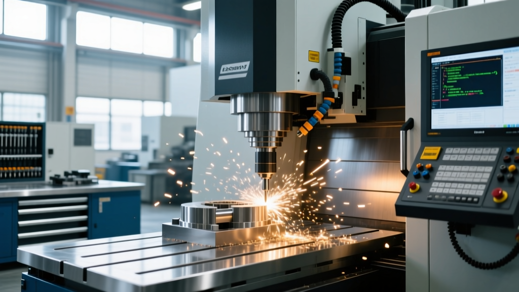
The shop transitioned to hyperMILL 2026, specifically leveraging the MAXX Machining trochoidal roughing module. Instead of maintaining a constant step-over that spiked in corners, the new CNC machining programs maintained a constant tool engagement angle of exactly 8% (0.96mm ae) while maximizing the axial depth of cut to 18mm (1.5xD). By utilizing the Sandvik Coromant Machining Knowledge guidelines for titanium chip thinning, the feedrate was aggressively scaled up.
Optimized Results: Ti-6Al-4V ELI
New Feedrate: 280 IPM
New Tool Life: 195 minutes (no edge chipping)
Roughing Cycle Time: 58 minutes per part
Net Result: A 44% reduction in cycle time and a 364% increase in tool life, saving the shop approximately $112,000 annually in carbide tooling costs alone.
Case Study 2: Eliminating Gouges in Inconel 718 Turbine Blades
Machining Inconel 718 for aerospace turbine blades requires extreme precision, but the real enemy is often the machine tool's servo lag during rapid directional changes. An aerospace supplier in Ohio was experiencing micro-gouges on the trailing edges of airfoils. The physical CNC machining programs were mathematically correct in the CAM system, but the physical machine—a DMG MORI DMU 50 3rd Generation with a Fanuc 31i-B5 control—was overshooting the vectors during high-speed contouring.
Diagnosing the Kinematic Failure
The issue was traced to a lack of controller-specific look-ahead commands in the post-processed G-code. The CAM system was outputting standard G01 linear interpolation moves without activating the Fanuc AI Nano Contour Control (G05.1 Q1). Furthermore, the rapid traverses (G00) between cuts were colliding with the fixture clamps because the CAM software assumed a perfect Cartesian movement, ignoring the machine's actual rotary axis (B and C axis) acceleration limits.
Implementing Digital Twin Simulation
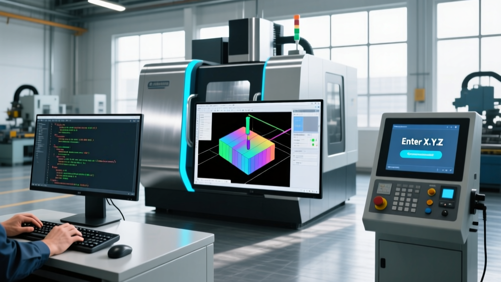
To resolve this, the engineering team integrated CGTech VERICUT Simulation into their programming workflow. VERICUT Force was used to analyze the NC code against the exact kinematic model of the DMU 50, including the Fanuc controller's specific block-processing speed and servo response times.
| Metric | Legacy CNC Program | VERICUT-Optimized Program |
|---|---|---|
| G-Code Look-Ahead | Standard (20 blocks) | G05.1 Q1 (1000+ blocks AI Nano) |
| Rapid (G00) Collisions | 2 near-misses per month | 0 (Kinematic smoothing applied) |
| Surface Finish (Ra) | 1.8 µm (Micro-gouging) | 0.6 µm (Consistent chip load) |
| Scrap Rate | 8.5% | 0.4% |
By simulating the exact CNC machining programs before they hit the shop floor, the shop eliminated $4,500-per-part scrap incidents and reduced the finishing pass cycle time by 18%, as the semi-finishing stock allowance could be tightened from 0.5mm to 0.15mm with absolute confidence.
Decision Framework: Auditing Your Current CNC Machining Programs
If your shop is experiencing unpredictable tool life or unexplained surface finish variations, your NC code is the primary suspect. Use this 4-step audit framework to evaluate your current programming output.
- Audit Rapid Traverse (G00) Kinematics
- Review your post-processor settings. Are G00 moves being output as true machine rapids, or are they being forced to G01 feedrates due to legacy safety settings?
- Check for rotary axis unwinding. If your B-axis is moving from 89° to -89° via G00, the machine will take the long way around (178° of travel) unless your post-processor is configured to calculate the shortest angular vector.
- Analyze M-Code Coolant Triggers
- Verify that M08 (flood) and M51/M52 (through-tool coolant) are triggering at least 2.0 seconds before the cutting feedrate (G01) engages. In high-pressure aerospace machining, delayed coolant activation causes instant thermal shock to the carbide substrate.
- Evaluate Corner Deceleration
- Open your G-code in a text editor and search for sharp directional changes. If your CAM system is not outputting smoothing commands (like G05.1 Q1 for Fanuc, or G64 P0.01 for Siemens), the machine will decelerate to near-zero at every corner, burning the tool edge in the dwell zone.
- Verify Spindle Load Consistency
- Run a test part and monitor the spindle load meter. If the load fluctuates between 15% and 65% during a single roughing pass, your CNC machining programs are using constant step-over toolpaths instead of constant engagement (adaptive) toolpaths.
"The gap between a mathematically correct toolpath and a physically optimized CNC machining program is where profit is made. We stopped treating our post-processor as a simple translator and started treating it as a kinematic controller. Once we mapped the exact servo limits of our 5-axis machines into our simulation software, our scrap rate on Inconel dropped to near zero."
— Lead Manufacturing Engineer, Tier-1 Aerospace Supplier
Strategic Implementation for 2026 and Beyond
Upgrading your CNC machining programs is not a one-time software purchase; it is a continuous engineering discipline. As machine tool manufacturers introduce higher-torque spindles and faster block-processing controls, your CAM toolpaths and post-processors must evolve to feed them data efficiently. Shops that invest in digital twin simulation and adaptive clearing strategies are currently outbidding competitors by 15-20% on complex aerospace and medical contracts, simply because their programmed cycle times reflect the true physical limits of their equipment.