How to Design a Precision CNC Machining Part: GD&T Specs
Learn how to specify a precision CNC machining part using GD&T, material matrices, and DFM principles to optimize tolerances and manufacturing costs.
The Physics of Tolerance: Why Your CNC Machining Part Fails
When engineering a custom CNC machining part, the most expensive mistakes occur before the spindle ever turns. Designers frequently apply blanket tolerances of ±0.005 inches (0.127 mm) to an entire 2D drawing, assuming the machine shop will naturally hold these dimensions. In reality, holding ±0.005 inches across a 12-inch aluminum extrusion is trivial, but holding that same tolerance on a 0.250-inch deep internal pocket in 304 stainless steel requires specialized tooling, climate-controlled metrology, and exponential cost increases.
A precision CNC machining part fails not at the individual feature level, but at the assembly level due to tolerance stack-up. If a three-piece aerospace housing requires mating surfaces to align within 0.002 inches, applying a standard ±0.002 inch tolerance to each individual part yields a worst-case stack-up of 0.006 inches. The part passes inspection on the CMM (Coordinate Measuring Machine), but fails entirely during final assembly. To prevent this, engineers must transition from coordinate dimensioning to Geometric Dimensioning and Tolerancing (GD&T), establishing datums that mimic the actual physical assembly sequence.
Warning: The 4:1 Depth-to-Diameter TrapNever design a deep pocket or bore without calculating the tool's length-to-diameter (L:D) ratio. For standard carbide end mills, chatter and deflection become uncontrollable beyond a 4:1 L:D ratio. If your CNC machining part requires a 1.0-inch deep pocket with a 0.125-inch corner radius, you are forcing the machinist to use a 0.250-inch diameter tool at a 4-inch stickout. This guarantees tool deflection, poor surface finish, and scrapped parts. Redesign the pocket depth to 0.75 inches or increase the corner radius to 0.250 inches to allow a rigid 0.500-inch end mill.
Material Selection Matrix for Tight-Tolerance Parts
The physical properties of your chosen alloy dictate the achievable tolerances of the CNC machining part. Materials with high internal stress or poor thermal conductivity will warp during the roughing phase or expand unpredictably under cutting heat. As of 2026, advanced 5-axis machining centers can hold ultra-tight tolerances, but material science remains the ultimate bottleneck.
| Material Grade | Machinability | Reliable Tolerance Limit | Cost Multiplier |
|---|---|---|---|
| 6061-T6 Aluminum | Excellent | ±0.0005 in (0.012 mm) | 1.0x (Baseline) |
| 7075-T6 Aluminum | Very Good | ±0.0008 in (0.020 mm) | 1.3x |
| 304 Stainless Steel | Poor (Work Hardens) | ±0.0015 in (0.038 mm) | 2.2x |
| 17-4 PH Stainless (H1150) | Fair | ±0.0010 in (0.025 mm) | 2.8x |
| Ti-6Al-4V (Grade 5 Titanium) | Very Poor | ±0.0020 in (0.050 mm) | 5.5x |
| PEEK (Victrex 450G) | Good (Thermal expansion risk) | ±0.0015 in (0.038 mm) | 4.0x |
Note: 7075-T6 contains higher zinc content than 6061-T6, making it significantly more prone to stress-relief warping if the part geometry involves aggressive material removal. Always specify stress-relieving thermal cycles for complex 7075 CNC machining parts prior to finish machining.
Applying GD&T to a CNC Machining Part
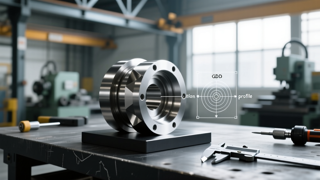
Relying on plus/minus dimensioning for complex geometries creates ambiguous inspection criteria. According to the ASME Y14.5 standard, GD&T provides a mathematical framework to define the exact functional intent of the part. For a precision CNC machining part, two geometric controls are paramount: True Position and Flatness.
True Position (⌖) with Maximum Material Condition (MMC)
When designing bolt-hole patterns on a CNC machining part, never use standard coordinate dimensions (e.g., X: 2.000 ±0.005, Y: 3.000 ±0.005). This creates a square tolerance zone of 0.010 square inches. By applying a True Position tolerance of 0.007 at MMC (Ⓜ), you create a circular tolerance zone that actually provides a 57% larger acceptable area for the machinist, reducing scrap rates while guaranteeing the bolt will clear the hole during assembly.
Flatness (⏥) vs. Parallelism
A common design flaw is specifying parallelism when flatness is required. Parallelism only dictates that a surface is parallel to a primary datum; it does not prevent the surface from being wavy or bowed. If your CNC machining part is a mating flange that requires an O-ring seal, you must specify Flatness (typically 0.001 inches or better) to ensure the surface is uniformly planar, preventing fluid bypass under high pressure.
Tool Deflection and Micro-Geometry Errors
Even on a $500,000 5-axis CNC mill, the cutting tool itself is a flexible beam. As noted by tooling experts at Harvey Tool, radial deflection increases with the cube of the tool's overhang length. If a CNC machining part features thin walls (under 0.040 inches) or deep, narrow ribs, the cutting forces will push the tool away from the material, resulting in a tapered wall that measures thicker at the top and thinner at the bottom.
Engineering Rule of Thumb: For thin walls in aluminum, maintain a minimum thickness of 0.040 inches (1 mm). For stainless steel or titanium, increase the minimum wall thickness to 0.080 inches (2 mm) to counteract the higher cutting forces and prevent harmonic chatter, which destroys both the surface finish and the carbide end mill.
To mitigate deflection without redesigning the part, specify that the machine shop must use variable helix, variable pitch end mills. These specialized tools break up harmonic resonance frequencies, allowing for deeper axial depths of cut with minimal radial deflection.
Surface Finish: Ra vs. Rz for Sealing Surfaces
Specifying a generic '32 Ra' (Roughness Average) on a drawing is insufficient for critical sealing surfaces on a CNC machining part. Ra only calculates the arithmetic average of the absolute deviations from the centerline. It completely ignores deep scratches or high peaks that can tear an O-ring or cause fatigue cracking in aerospace components.
- Ra (Roughness Average): Best for general cosmetic surfaces and non-critical mating faces. Standard face milling achieves 63-125 Ra.
- Rz (Average Maximum Height): Measures the average distance between the highest peak and lowest valley. Critical for hydraulic manifold bores and bearing journals. Specify Rz when fatigue life and fluid retention are priorities.
- Rmr (Material Ratio / Bearing Area Curve): Essential for sliding wear surfaces. It dictates the percentage of material that will actually bear the load at a specific depth, ensuring proper oil retention in the microscopic valleys.
If your CNC machining part requires a 16 Ra finish on a sealing face, you must also specify the machining method. A standard 4-flute end mill will leave a scalloped cusp height that may measure 16 Ra but contains sharp peaks. Specify a final pass using a diamond burnishing tool or a specialized wiper-insert face mill to flatten the peaks and achieve a true bearing surface.
Metrology: Verifying the CNC Machining Part
A tolerance is only as valuable as the ability to measure it. Designing a CNC machining part with ±0.0002-inch (5 micron) true position tolerances on internal, non-through features requires advanced metrology. Standard calipers and micrometers are entirely useless at this scale due to operator-dependent clamping force variations.
Verification at this level requires equipment calibrated to NIST traceable dimensional metrology standards, typically involving a bridge-style Coordinate Measuring Machine (CMM) operating in a climate-controlled room held at exactly 20°C (68°F). Thermal expansion of a 10-inch aluminum part changes its length by roughly 0.0012 inches for every 10°F shift in ambient temperature. If your drawing demands ultra-precision, you must explicitly state that final inspection must occur after a 12-hour thermal soak in a 20°C environment.
Cost of Tolerance MultipliersMoving from a standard ±0.005 in tolerance to ±0.001 in increases machining costs by approximately 2.2x due to slower feed rates and secondary finishing operations. Pushing from ±0.001 in to ±0.0002 in increases costs by 6.5x to 8.0x, requiring jig grinding, wire EDM, and dedicated CMM programming. Only apply ultra-tight tolerances to the exact datum features required for assembly; leave all other features at standard commercial tolerances.
Design for Manufacturability (DFM) Edge Cases
Beyond tolerances and materials, the physical geometry of the CNC machining part dictates its manufacturability. Address these three edge cases during the CAD phase to prevent immediate RFQ rejection:
- Internal Thread Milling vs. Tapping: For holes larger than 1/2-13 or in hardened materials like 17-4 PH, specify thread milling instead of standard tapping. Thread milling uses a helical interpolation toolpath, eliminating the risk of broken taps trapped inside blind holes and producing vastly superior thread surface finishes.
- Undercuts and Dovetails: Standard 3-axis CNC mills cannot reach undercuts without specialized lollipop or slot-cutting tools. If your design requires an O-ring gland in an internal undercut, ensure the gland width is at least 0.100 inches to accommodate the shank clearance of a standard undercut end mill.
- Part Fixturing (The 6th Side Problem): A CNC machining part must be held securely to the machine bed. If your design encompasses all six sides of the raw billet with complex contours, the machinist has nowhere to clamp the part for the final operation. Always design a sacrificial 'tab' or leave one flat, non-critical surface specifically for vise clamping, to be machined away or left as-is in a secondary setup.
By integrating GD&T principles, respecting material-specific tool deflection limits, and designing for physical metrology, engineers can bridge the gap between theoretical CAD models and functional, cost-effective physical hardware.