Tooling & Workholding Training for a CNC Machined Parts Manufacturer
Master operator training for a CNC machined parts manufacturer. Learn workholding, tool presetting, and accessory setup best practices to reduce scrap.
A high-mix CNC machined parts manufacturer operates on razor-thin margins where setup time and first-part yield dictate overall profitability. When machine operators lack advanced training in workholding dynamics, tool presetter utilization, and high-pressure coolant integration, shops bleed money through extended setups, premature tool wear, and scrapped components. Standard OEM machine training covers basic G-code, macro programming, and axis jogging, but it rarely addresses the nuanced reality of custom fixturing, hydraulic chuck pressure curves, or laser tool measurement. As of 2026, with spindle time costs averaging $150 to $250 per hour in precision job shops, institutionalizing advanced accessory training is no longer optional. This guide provides actionable, deep-level training frameworks for shop floor supervisors and lead machinists.
Workholding Dynamics: Eliminating Chuck Runout and Deflection
Operators often treat a 3-jaw power chuck as a simple clamp. In reality, it is a precision instrument highly sensitive to centrifugal force and clamping load. For a CNC machined parts manufacturer running 7075-T6 aluminum aerospace fittings at 4,500 RPM, standard static clamping pressure calculations are dangerously inadequate.
Centrifugal Force Compensation
As RPM increases, the chuck jaws are thrown outward by centrifugal force, drastically reducing the effective clamping force on the workpiece. On a standard Kitagawa B-210 hydraulic chuck, a static clamping force of 15,000 lbs can drop by up to 40% at 4,000 RPM. Operators must be trained to use the manufacturer's RPM-to-pressure compensation charts. This requires increasing the hydraulic drawtube pressure dynamically to maintain the minimum required safety factor (typically 3:1 against maximum cutting forces). Failing to train operators on this dynamic pressure curve is a primary cause of workpiece ejection and catastrophic machine crashes at high speeds.
Soft Jaw Boring Protocols
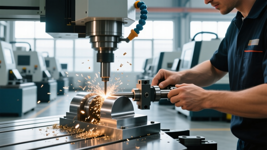
Machining soft jaws (6061-T6 aluminum or 1018 steel) is a daily task in high-mix environments. Operators must be trained to never bore soft jaws 'dead.' They must always pre-load the chuck using a master ring gauge, a boring spider, or a simple O-ring placed near the base of the jaws. This forces the jaw to sit against the master jaw in the exact same position it will occupy when clamping the actual workpiece, eliminating backlash and reducing bored-in runout from 0.002 inches to less than 0.0005 inches.
Critical Safety Warning: Never exceed the maximum RPM rating stamped on the chuck body. Centrifugal jaw ejection at 5,000 RPM carries enough kinetic energy to penetrate standard machine guarding. Always verify compliance with OSHA 1910.212 General Requirements for All Machines regarding chuck guarding and interlocks.Tool Presetting: The Hidden ROI of Offline Measurement
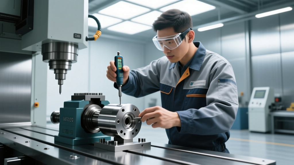
In-tool probing (using the machine's spindle probe to touch off tools) consumes valuable spindle time. For a busy CNC machined parts manufacturer, moving to an offline optical and contact tool presetter (such as a Haimer VIO or Zoller smileLine) reclaims up to 45 minutes of spindle time per shift. Presetters are not just for measuring length and diameter; they are critical for identifying toolholder runout before the tool ever enters the CNC enclosure.
| Tool Type | Target Runout | Max Acceptable | Impact of Exceeding Tolerance |
|---|---|---|---|
| 1/2' Solid Carbide Endmill | < 3µm | 5µm | Uneven flute loading reduces tool life by 40% and causes poor surface finish. |
| 3' Indexable Face Mill | < 10µm | 15µm | Inserts on the high side take the entire radial load, leading to catastrophic fracture. |
| 1.5' U-Drill | < 8µm | 12µm | Pilot insert fails prematurely, causing the drill to walk and scrap the bore. |
| 0.250' Reamer | < 2µm | 4µm | Oversized bore generation and severe chatter marks on the bore wall. |
Advanced Accessory Integration: High-Pressure Coolant Systems
Standard flood coolant operates at roughly 300 PSI. When machining exotic alloys like Inconel 718 or Titanium Ti-6Al-4V, operators must integrate high-pressure through-tool or articulated nozzle accessories operating between 1,000 and 2,000 PSI. According to data supported by the NIST Manufacturing Extension Partnership, optimizing coolant delivery is one of the highest-ROI interventions for exotic alloy machining.
Chip Control and Orifice Matching
At 1,000 PSI, the coolant stream physically shears the chip at the shear zone, preventing the long, stringy 'birds nests' that wrap around boring bars and break tooling. Operators must be trained to match the nozzle orifice size to the pump pressure. Using a 0.040-inch orifice at 1,000 PSI provides the necessary velocity to break Inconel chips, whereas a 0.080-inch orifice at the same pressure will merely wash over the chip without breaking it, leading to recutting and rapid insert wear.
Laser Tool Measurement and Breakage Detection
For unattended or lights-out machining shifts, non-contact laser tool setting systems (like the Renishaw NC4 or Blum MicroCompact) are mandatory accessories. However, operators frequently misuse these systems by failing to account for environmental factors inside the machine enclosure.
- Coolant Mist Interference: Laser beams can be scattered by heavy coolant mist, resulting in false tool breakage alarms. Operators must program a 2-second targeted air-blast cycle at the laser lens before initiating the measurement macro.
- Beam Waist Calibration: The laser beam is not perfectly uniform; it has a 'waist' where the diameter is smallest (typically 0.0004 inches). Operators must be trained to set the Z-height of the tool tip exactly at the beam waist for the highest accuracy, rather than just breaking the beam at an arbitrary height.
- Radius vs. Diameter Measurement: Training must emphasize that measuring the radius of a worn endmill on one side does not account for eccentric wear. Operators should utilize the laser's rotation macro to measure the tool at 0, 90, 180, and 270 degrees to calculate true maximum runout and wear.
Building a Standardized Setup Matrix
To institutionalize this knowledge, a CNC machined parts manufacturer must build a Setup Matrix. This is a living document that maps specific part geometries and materials to required tooling and accessory configurations, ensuring adherence to standards like ISO 13399:2015 Cutting tool data representation for digital tool library consistency.
Example Setup Matrix Rules:
1. Thin-Wall Cylinders (<0.050' wall): Mandate vacuum chucks or low-pressure (20 PSI) pneumatic step chucks with urethane jaw pads to prevent elastomer deformation.
2. Deep Cavity Milling (L:D ratio > 5:1): Mandate shrink-fit toolholders to eliminate nut-induced runout, paired with 1,000 PSI through-spindle coolant for chip evacuation.
3. High-Accuracy Bores (±0.0002'): Mandate hydraulic expansion chucks or milling chucks with adjustable runout compensation, avoiding standard ER collets which inherently exhibit 5-10µm of runout.
By shifting operator training from basic machine operation to advanced accessory integration and dynamic workholding physics, shops can drastically reduce scrap rates, extend tool life, and maximize the uptime of their most expensive capital assets.