Troubleshooting the A-Axis on Your Four Axis CNC Milling Machine
Diagnose and fix common A-axis rotary table errors, servo alarms, and backlash issues on a four axis CNC milling machine with this expert repair guide.
Diagnosing A-Axis Servo Overload and Mechanical Binding
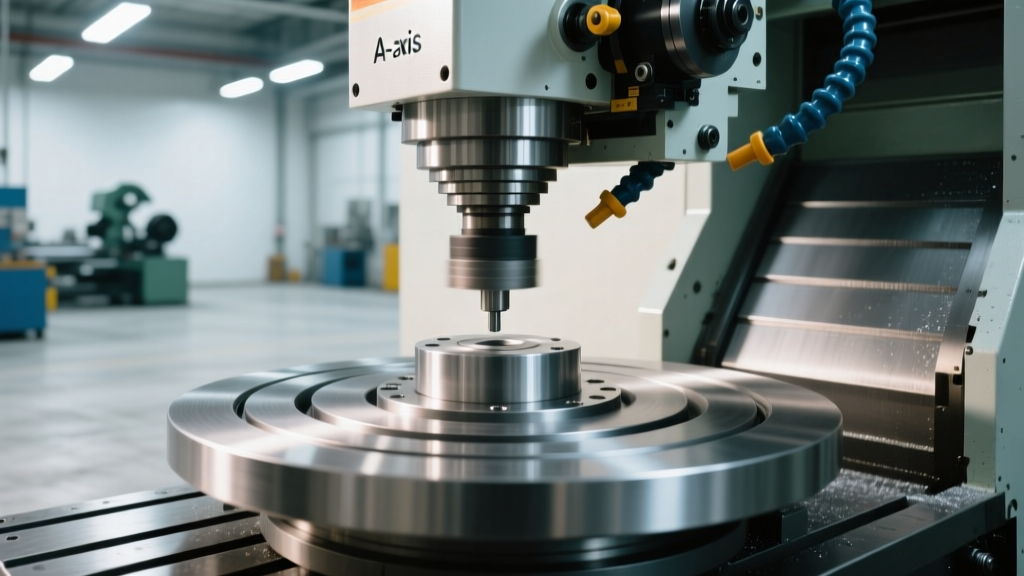
Integrating a rotary indexer transforms a standard vertical machining center into a highly capable four axis CNC milling machine. However, the addition of the A-axis introduces unique mechanical and electrical failure modes that do not exist on standard 3-axis linear setups. The most frequent showstopper in 4-axis machining is an A-axis servo overload alarm, which typically manifests during heavy simultaneous contouring or aggressive index-and-hold operations.
When a Fanuc or Haas controller throws an overcurrent alarm (such as Fanuc Alarm 401 or Haas Alarm 101) specifically on the rotary axis, the immediate instinct is to blame the servo drive. In reality, 80% of these faults stem from mechanical binding within the rotary table itself. Coolant ingress, degraded bearing grease, or a misaligned tailstock can create enough rotational resistance to spike the servo motor's amperage draw.
Step-by-Step Servo Isolation Test
To determine if the fault is electrical or mechanical, you must decouple the motor from the drive train. Power down the machine, lock out the main breaker, and remove the servo motor from the rotary table housing. Once the motor is free-hanging, power the machine back on and run a dry-cycle A-axis rotation command.
- If the alarm persists with the motor detached: The issue is electrical. Check the motor windings for short circuits using a megohmmeter (reading should be >100 MΩ at 500V DC). Inspect the encoder feedback cable for micro-fractures caused by continuous cable carrier flexing.
- If the motor runs smoothly detached: The issue is mechanical binding inside the rotary table. Proceed to inspect the worm gear mesh, the rotary union, and the tailstock alignment.
Correcting Excessive Backlash in Rotary Indexers
Backlash in the A-axis is the primary enemy of surface finish quality during simultaneous 4-axis contouring. Unlike linear axes where backlash compensation can effectively mask wear via CNC parameters, rotary axis backlash causes non-linear tool path deviations that result in visible scallops and dwell marks on the workpiece.
Understanding your rotary table's drive mechanism is critical for troubleshooting. Mid-range tables typically use a worm gear and worm wheel setup, while high-end 2026 models increasingly utilize harmonic (strain wave) drives.
Worm Gear vs. Harmonic Drive Tolerances
A new worm gear rotary table (such as the popular Haas HRT210 series) is factory-set to 15–30 arc-seconds of backlash. Once wear exceeds 60 arc-seconds, the table requires physical adjustment. Conversely, harmonic drive tables (like those from Nikken or Tsudakoma) boast near-zero backlash (<5 arc-seconds) but cannot be manually adjusted; if a harmonic drive develops play, the flex spline is fatigued and the entire drive unit must be replaced. As of 2026, a harmonic drive replacement typically costs between $3,500 and $5,500, whereas a standard worm gear wheel rebuild ranges from $1,200 to $2,500.
Adjusting Worm Gear Mesh (Eccentric Bushing Method)
If your four axis CNC milling machine utilizes a worm gear table with excessive backlash, follow this precise adjustment procedure:
- Mount a 0.0001-inch resolution dial indicator on the machine spindle, positioning the plunger against the outer rim of the rotary platter.
- Apply 15 lbs of rotational force to the platter in both clockwise and counterclockwise directions to measure total indicated runout (TIR) representing backlash.
- Locate the eccentric adjustment bushing on the side of the rotary housing opposite the servo motor. Loosen the four perimeter locking bolts by exactly one-half turn.
- Insert the manufacturer-provided spanner wrench into the bushing and rotate it in 5-degree increments. Each 5-degree turn alters the worm shaft centerline distance by approximately 0.0004 inches.
- Re-torque the locking bolts to 35 ft-lbs using a calibrated torque wrench. Re-measure the backlash. Target 20 arc-seconds of play. Setting it to absolute zero will cause the gear oil to overheat and seize the table during continuous rotation.
Expert Insight: Always use the manufacturer-specified grease when reassembling the worm gear housing. For most standard rotary tables, an NLGI #2 lithium complex grease with EP additives (such as Mobilux EP2 or Mobilith SHC 220) is required. Standard way lube will not withstand the sheer forces of the worm gear mesh and will rapidly degrade, leading to premature bronze wheel wear.
Troubleshooting Rotary Axis Homing and Limit Switch Failures
A four axis CNC milling machine relies on precise homing sequences to establish the A-axis zero point. Unlike linear axes that use physical hard stops and dog-blocks, most rotary indexers use a high-resolution absolute encoder or an inductive proximity switch to find the Z-phase pulse. When the A-axis fails to home, overshoots the home position, or triggers a 'Limit Switch Tripped' alarm before reaching home, the culprit is almost always the proximity sensor or its wiring.
The environment inside a CNC enclosure is hostile to electronics. Tramp oil, synthetic coolants, and microscopic aluminum or titanium chips frequently penetrate the IP67 seals of standard inductive proximity switches. Over time, the coolant degrades the potting compound inside the sensor, causing the switching distance to drift from the factory-set 1.5mm down to 0.2mm. This results in intermittent homing failures that only occur when the machine is cold or when ambient shop temperatures drop.
The Fix: Replace the standard OEM proximity switch with an IP69K-rated, washdown-grade sensor (such as the IFM Efector IN5228 or equivalent Turck uprox series). These sensors feature fully stainless-steel housings and Teflon-coated faces that resist coolant adhesion and chip welding. When installing the new sensor, use a non-magnetic feeler gauge to set the air gap precisely to 1.0mm (+/- 0.1mm) from the rotating cam block. Verify the sensor's LED indicator triggers consistently while manually rotating the platter through five full 360-degree revolutions.
Common 4th Axis Alarm Codes and Immediate Resolutions
Reference this matrix when diagnosing controller faults specific to the rotary axis on your four axis CNC milling machine.
| Alarm Code | Controller | Root Cause | Immediate Action Required |
|---|---|---|---|
| 401 / 411 | Fanuc | Servo Overcurrent / Move Error | Decouple motor; check for mechanical binding in the worm gear or tailstock misalignment. |
| 101 / 102 | Haas | Rotary Axis Overload | Verify tailstock is not over-clamped; check rotary union for internal seal seizure. |
| 360 / 361 | Fanuc | Encoder Feedback Disconnect | Inspect the A-axis encoder cable at the drag chain bend radius; replace if shielding is compromised. |
| 436 | Haas | A-Axis Limit Switch Tripped | Clean the inductive proximity sensor face; verify 1.0mm air gap to the homing cam. |
| SV0410 | Fanuc | Servo Axis Following Error | Check servo tuning; verify the workpiece is balanced to prevent centrifugal load spikes. |
Managing Coolant Pressure and Rotary Union Leaks
Modern 4-axis setups frequently utilize through-spindle coolant (TSC) routed directly through the rotary table and into the workpiece or tombstone. The rotary union—the mechanical seal that allows high-pressure fluid to pass from the stationary machine base into the rotating A-axis platter—is a high-wear component.
Standard rotary unions on mid-tier indexers are rated for a maximum of 300 PSI. If your shop upgrades to a 1000 PSI high-pressure coolant pump to improve chip evacuation in deep-cavity titanium milling, the standard union seals will instantly blow out, flooding the A-axis servo motor and encoder housing with coolant. This specific failure mode routinely destroys $4,000 servo motors.
Before enabling high-pressure coolant on a four axis CNC milling machine, verify the exact part number of the installed rotary union. If high-pressure routing is required, you must retrofit a multi-port, high-pressure rotary union (such as those manufactured by Deublin or DSTI) rated for your specific pump output. Furthermore, install a 5-micron inline filter immediately upstream of the rotary union. Microscopic swarf circulating in the coolant will score the precision-lapped carbon graphite seal faces inside the union, causing internal leaks that bypass fluid directly into the rotary table's gear oil reservoir.
Preventative Maintenance Framework for 4-Axis Setups
To maximize uptime and maintain contouring accuracy, implement this strict maintenance schedule for your rotary equipment. For deeper OEM specifications, always refer to the Haas Automation Service Manuals or consult FANUC America Servo Systems documentation for drive-specific tuning parameters.
- Weekly (40 Hours): Purge the rotary table air clamp system. Cycle the pneumatic clamp/unclamp solenoid five times while the machine is idle to expel condensed moisture from the air lines, preventing internal corrosion of the piston seals.
- Monthly (160 Hours): Inspect the A-axis servo motor coupling. If your machine uses an Oldham-style slit coupling, check for aluminum dust accumulation in the slits, which can cause micro-sticking and following errors.
- Bi-Annually (1000 Hours): Drain and replace the worm gear housing oil. Use only the manufacturer-specified synthetic gear oil (typically ISO VG 220 or VG 320). Do not mix synthetic and petroleum-based lubricants.
- Annually (2000 Hours): Perform a laser interferometry or ballbar test specifically on the A-axis to map volumetric error and backlash. Adjust the eccentric bushing or schedule a harmonic drive replacement based on the data. For bearing-specific wear analysis, reference SKF Rolling Bearing Maintenance guidelines to identify early-stage spalling frequencies in the rotary cross-roller bearings.
By treating the rotary axis as a precision drivetrain rather than a simple clamping accessory, shops can eliminate the majority of unplanned downtime associated with 4-axis machining and maintain the tight tolerances required for aerospace and medical component manufacturing.