CNC vs Milling Machine: Technical Specs & How They Operate
Compare CNC vs milling machine technical specs. Explore kinematics, spindle drives, tolerances, and control systems to choose the right mill for your shop.
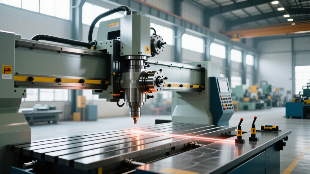
When machinists and shop managers evaluate a cnc vs milling machine investment, the comparison is fundamentally between Computer Numerical Control (CNC) automation and traditional manual operation. While both remove material via rotary cutting tools, their underlying kinematics, drive systems, and control architectures are entirely different. Understanding the technical specifications of each is critical for determining which platform meets your tolerance, throughput, and geometric complexity requirements.
Kinematics and Axis Drive Systems
The most profound technical divergence between manual and CNC milling machines lies in how they translate motor rotation into linear axis movement. This directly dictates positioning accuracy, repeatability, and rapid traverse capabilities.
Manual Milling: Acme Leadscrews and Backlash
Standard manual mills, such as the iconic Bridgeport Series I, utilize Acme-threaded leadscrews paired with bronze or plastic split-nuts. This design inherently generates backlash—the slight rotational play in the handwheel before the table physically moves. While operator skill and backlash eliminators can mitigate this, manual mills typically achieve a practical positioning accuracy of ±0.001" to ±0.002" (0.025mm to 0.050mm). The friction coefficient of the Acme thread also limits rapid traverse speeds, requiring the operator to physically crank handwheels, which caps table movement to roughly 50 inches per minute (IPM) under load.
CNC Milling: Preloaded Ballscrews and Servo Loops
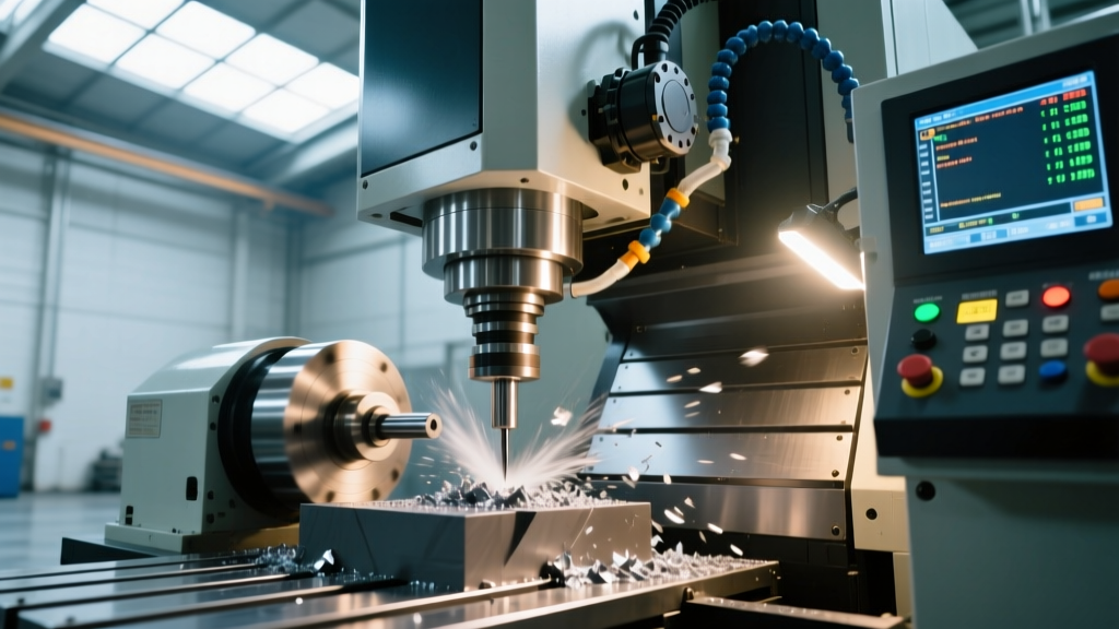
CNC vertical machining centers (VMCs) replace Acme threads with precision-ground recirculating ballscrews. By using spherical bearings between the screw and the nut, friction is reduced by up to 90%. High-end CNC mills use C3-grade ballscrews (ISO 3408 standard) that guarantee an accuracy of 0.0005" per 12 inches of travel. Furthermore, CNC ballscrews are preloaded using a double-nut configuration with an oversized ball spacer, entirely eliminating mechanical backlash. Paired with AC servo motors and closed-loop PID controllers, CNC machines achieve bidirectional repeatability of ±0.0002" (0.005mm).
Technical Insight: Thermal Growth CompensationAs ballscrews rotate at high rapid speeds (e.g., 1,000 IPM), friction generates heat, causing the screw to expand and alter axis positioning. Advanced CNC mills (like the Haas VF-2) mitigate this by pumping chilled glycol through the core of the ballscrew and utilizing spindle chillers to maintain a strict 20°C (68°F) thermal equilibrium, a feature physically impossible on manual machines.
Spindle and Drive Specifications Matrix
The spindle is the heart of the milling machine. Manual mills prioritize high torque at low RPMs for heavy roughing with large diameter cutters, while CNC mills prioritize high RPM, high-frequency torque, and rapid tool changing for modern carbide tooling.
| Specification | Standard Manual Mill (e.g., Bridgeport Series I) | Standard CNC VMC (e.g., Haas VF-2) |
|---|---|---|
| Spindle Power | 1 HP to 2 HP (Continuous) | 20 HP to 30 HP (Vector Drive) |
| Max RPM | 2,800 RPM (Step-pulley) / 4,200 RPM (Variable) | 8,100 RPM (Standard) / 12,000+ RPM (Direct-Drive) |
| Tool Taper | R8 (Manual drawbar retention) | CAT40 or BT40 (Pneumatic retention knob release) |
| Tool Change Time | 45 to 120 seconds (Manual wrench operation) | 1.5 to 3.5 seconds (Automatic Tool Changer - ATC) |
| Spindle Orientation | Fixed (unless using specialized attachments) | Rigid tapping capable (Spindle orientation synchronized to Z-axis) |
As detailed in Sandvik Coromant's milling knowledge base, modern indexable and solid carbide endmills require high surface speeds (SFM) to operate efficiently. For example, machining 6061 aluminum with a 0.5" carbide endmill requires roughly 10,000 RPM. A manual mill cannot reach this speed, forcing the operator to run the tool below its optimal cutting parameters, drastically reducing tool life and surface finish quality. CNC spindles, driven by vector variable frequency drives (VFDs), maintain constant torque across a wide RPM band, perfectly matching modern tooling requirements.
Control Architecture: DRO vs. G-Code Interpolation
The method by which toolpaths are executed separates the two technologies fundamentally.
Manual Mills with Digital Read Outs (DRO)
Modern manual mills are often retrofitted with 2-axis or 3-axis DRO systems utilizing glass linear scales. While a high-resolution glass scale can read down to 0.0002" (5 microns), the system remains open-loop regarding actual machine movement. The DRO tells the operator where the table is, but the operator must manually stop the feed. Human reaction time (approximately 200-250 milliseconds) introduces a physical lag, making it impossible to hold tight tolerances during continuous contouring or circular interpolation.
CNC Mills and Look-Ahead Processing
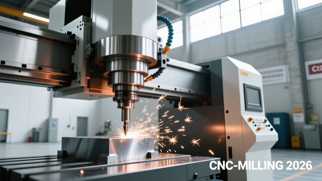
CNC controls (such as Fanuc, Siemens, or Haas NGC) utilize closed-loop servo encoders mounted directly to the axis motors. The control reads G-code and performs complex mathematical interpolation. A critical technical advantage of CNC is Look-Ahead Processing. Before executing a complex 3D contour consisting of thousands of micro-line segments, the CNC control scans hundreds of blocks ahead to calculate acceleration and deceleration vectors. This prevents the machine from violently jerking to a stop at sharp geometric corners, maintaining a constant chip load and preventing dwell marks on the workpiece—a physical impossibility for manual operation.
Decision Framework: Deploying the Right Technology
Selecting between a CNC and a manual milling machine requires analyzing the specific geometry, batch size, and tolerance stack-up of your production run. Use the following technical framework to guide your decision:
- Deploy Manual Milling When:
- Operation: Simple 2D facing, edge squaring, or single-hole drilling.
- Tolerance: Geometric tolerances are looser than ±0.005" (0.127mm).
- Setup Time vs. Cycle Time: The part requires 45 minutes to fixture and program on a CNC, but only 3 minutes to cut manually.
- Material: Heavy, interrupted roughing cuts on raw castings where the simplicity of manual feed rate adjustment prevents catastrophic tool breakage.
- Deploy CNC Milling When:
- Operation: 3D contouring, helical interpolation, or rigid tapping.
- Tolerance: True position or profile tolerances require ±0.0005" (0.012mm) repeatability.
- Batch Size: Production runs exceeding 10 identical parts, where the amortized cost of CNC setup and ATC tool changes yields a lower cost-per-part.
- Surface Finish: Requirements dictate a 32 Ra (microinches) or better finish, necessitating the constant feed rates and high RPMs only a CNC can provide.
The Hybrid Shop Approach
Highly optimized machine shops in 2026 rarely rely on just one technology. The most efficient workflow utilizes manual mills for rapid fixture fabrication, soft-jaw machining, and quick prototype modifications, reserving the CNC VMCs for uninterrupted, lights-out production runs. By understanding the exact kinematic and spindle limitations of both systems, manufacturing engineers can allocate workloads that maximize spindle utilization and minimize non-cutting time.