Core Components of CNC Milling Machine: Operator Training Guide
Master the core components of CNC milling machine hardware. This operator training guide covers spindle specs, ballscrew backlash, and daily inspections.
Beyond the Code: Mastering the Hardware
Operator proficiency extends far beyond G-code programming and work coordinate offsets. True mastery requires an intimate understanding of the physical components of CNC milling machine hardware and how they behave under cutting loads, thermal expansion, and continuous vibration. When an operator understands the mechanical realities of the spindle, drive systems, and feedback loops, they can predict tool wear, prevent catastrophic crashes, and hold tolerances under 0.0005 inches consistently.
This guide bypasses basic definitions and dives directly into the technical parameters, maintenance thresholds, and operational best practices required for advanced CNC milling.
The Spindle Assembly and Tool Retention System
The spindle is the most expensive and sensitive component on the mill. While operators often focus on RPM limits, the true point of failure in heavy roughing operations is the tool retention system (drawbar and pull stud).
Retention Force and Pull Stud Integrity
In a standard CAT40 or BT40 taper system, the spindle's internal Belleville washers or pneumatic cylinder must exert sufficient force to keep the tool seated during high radial loads. According to Sandvik Coromant's tool holding guidelines, improper retention force is a leading cause of micro-movement, which accelerates taper wear and ruins surface finishes.
- CAT40 Target Pull Force: 2,500 to 3,000 lbf (pounds-force).
- CAT50 Target Pull Force: 4,500 to 5,500 lbf.
- HSK-A63 Target Clamping Force: 3,500 to 4,000 lbf.
Spindle Thermal Stabilization Protocol
Bearings expand as they reach operating temperature. If you start a tight-tolerance job on a cold spindle, the Z-axis will drift by 0.001" to 0.003" over the first 45 minutes as the spindle housing expands. Operators must execute a staged warm-up cycle:
- Stage 1: 5 minutes at 2,000 RPM (distributes bearing grease).
- Stage 2: 5 minutes at 5,000 RPM (begins thermal expansion).
- Stage 3: 5 minutes at 80% of max RPM (stabilizes the thermal envelope).
Axis Drive Mechanics: Ballscrews and Linear Guideways
The translation of rotary servo motor motion into linear axis movement relies on precision-ground ballscrews. Over time, the recirculating balls wear the screw raceways, introducing backlash (deadband) that ruins circular interpolation and causes axis reversal spikes in surface finishes.
Measuring and Compensating Backlash
Operators should verify axis backlash monthly using a magnetic base dial indicator (0.0001" resolution) mounted to the table, with the plunger against the spindle housing. Command the axis to move +1.000", then reverse -1.000". The difference between the commanded movement and the indicator reading is your backlash.
| Axis | New Machine Tolerance | Maximum Acceptable Wear | Fanuc Compensation Parameter |
|---|---|---|---|
| X-Axis | ≤ 0.0002" | 0.0006" | 1851 (Pitch Error / Backlash) |
| Y-Axis | ≤ 0.0002" | 0.0006" | 1851 (Pitch Error / Backlash) |
| Z-Axis | ≤ 0.0003" | 0.0008" | 1851 (Pitch Error / Backlash) |
If backlash exceeds the maximum acceptable wear limit, software compensation (via parameter 1851 on Fanuc controls) is only a temporary band-aid. The ballscrew preload must be mechanically adjusted by a technician, or the screw assembly must be replaced. Relying purely on software compensation for severe mechanical wear will cause servo lag and trigger following error alarms (e.g., Fanuc Alarm 411).
Coolant Delivery and Thermal Management
Coolant is not just for lubrication; it is a critical thermal management system for both the cutting tool and the workpiece. Operators must monitor concentration, pressure, and delivery angle to prevent thermal shock to carbide inserts.
Concentration and Refractometer Readings
Running water-thin coolant (below 5% concentration) leads to flash rusting on machine components and premature tool wear. Running overly rich coolant (above 12%) wastes money, causes foaming, and leaves sticky residues that clog way covers.
Operators must use a handheld optical refractometer daily. Note that refractometers measure the Brix scale, which must be multiplied by the specific fluid's refractive index factor. For example, if using a synthetic fluid with a 2.5x multiplier, a Brix reading of 4.0 indicates a true 10% concentration.
Through-Spindle Coolant (TSC) Pressures
Standard flood coolant operates at 30 to 60 PSI, which is sufficient for chip flushing in aluminum or mild steel. However, when machining deep cavities in titanium or Inconel, operators must engage high-pressure TSC.
- 300 PSI TSC: Ideal for standard deep-hole drilling and tapping in steel.
- 1,000 PSI TSC: Required for breaking stringy chips in aerospace superalloys and ensuring coolant reaches the cutting edge through the shear zone.
Feedback Systems: Encoders and Glass Scales
The CNC controller relies on feedback loops to know the exact position of the table. Standard machines use rotary encoders mounted to the servo motors (semi-closed loop). High-precision machines utilize linear glass scales mounted directly to the axes (fully closed loop).
Protecting Linear Scales from Contamination
As noted in Heidenhain's technical documentation on linear encoders, glass scales offer sub-micron accuracy but are highly vulnerable to contamination. If coolant or fine cast iron dust breaches the scale's lip seals, the reading head will misinterpret the light diffraction, resulting in sudden axis runaways or severe gouging.
Operator Best Practice: Inspect the scale air purge lines daily. High-precision mills use a low-pressure air purge (typically 15-20 PSI) to create positive pressure inside the scale housing, pushing contaminants out. If the airflow indicator on the machine cabinet drops to zero, halt production immediately. Running without positive air pressure will destroy a $4,000 glass scale within a single shift in a dirty environment.Shift-Start Inspection Matrix
To maintain machine geometry and prevent unplanned downtime, operators must execute a rigorous pre-flight inspection. This matrix outlines the exact checks required at the start of every first shift.
| Component | Inspection Action | Target Metric / Condition | Corrective Action if Failed |
|---|---|---|---|
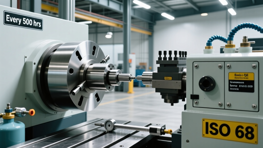
| Way Lube System | Check reservoir level and verify pressure gauge spikes during auto-cycle. | Level above 'Min' line; pressure spikes to 20-30 PSI every 15 mins. | Refill with ISO 68 way oil. If pressure doesn't spike, check for broken distribution lines under the way covers. |
| Spindle Taper | Wipe interior with a clean, lint-free cloth and isopropyl alcohol. | Zero visible chips, dust, or oil residue. | Clean thoroughly. A single 0.005" chip trapped in the taper causes 0.002" TIR runout at the tool tip. |
| Coolant Sump | Skim tramp oil and check concentration via refractometer. | 8-10% concentration; less than 2mm tramp oil layer. | Adjust concentrate/water ratio. Run tramp oil skimmer for 2 hours. |
| Tool Magazine | Inspect empty tool pockets for debris and check swing arm alignment. | Pockets clean; arm locks flush with spindle nose. | Clean pockets with a brush. Misalignment requires maintenance calibration to prevent tool drops. |
| Chip Conveyor | Verify hinge belt tension and coolant flow through the screen. | Belt tracks centrally; no chip buildup in the sump. | Adjust tensioning bolts on the conveyor tail. Clear blockages to prevent sump overflow. |
The Cost of Neglect
Ignoring these mechanical realities compounds rapidly. A $50 bottle of way lube neglected for a month leads to stick-slip friction on the linear guideways, destroying the PTFE wipers and scoring the hardened steel rails. According to Modern Machine Shop's preventive maintenance analyses, machines with documented, operator-led daily inspections experience up to 40% less unplanned downtime over a 5-year lifecycle compared to machines where maintenance is purely reactive.
Mastering the components of your CNC mill transforms you from a passive operator into an active process engineer. By monitoring retention forces, compensating for thermal drift, and protecting feedback loops, you guarantee the machine performs exactly as the CAM software intended, shift after shift.