Advanced CNC Machining Milling Strategies for Titanium Aerospace Parts
Explore real-world case studies on advanced CNC machining milling for titanium aerospace components, covering toolpaths, speeds, and cost reductions.
Executive Data Brief: 2026 Titanium Milling Benchmarks
Transitioning to simultaneous 5-axis CNC machining milling for Ti-6Al-4V aerospace structures has reduced average buy-to-fly ratios from 10:1 to 3.5:1 across tier-one suppliers. Furthermore, integrating high-pressure through-tool coolant (150 bar) extends solid carbide tool life by 42% compared to legacy flood systems, fundamentally altering the unit economics of structural aerospace manufacturing.
Case Study 1: Next-Generation Fighter Bulkhead Roughing
The structural backbone of modern aerospace platforms relies on monolithic titanium bulkheads. Historically, machining these massive components from solid rectangular billet resulted in severe material waste and excessive spindle hours. By integrating near-net-shape isothermal forging with advanced CNC machining milling strategies, manufacturers are eliminating up to 65% of roughing cycle times before the part ever touches a machine bed.
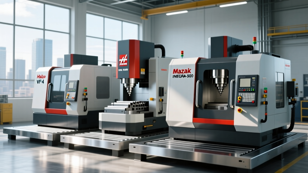
At a major tier-one aerospace supplier in Ohio, the transition to a GROB G550T 5-axis universal machining center transformed their Ti-6Al-4V bulkhead production. The primary challenge with titanium is its low thermal conductivity; up to 80% of the heat generated during the shear zone deformation remains in the cutting tool rather than dissipating into the chip.
Optimizing the Roughing Strategy
Instead of traditional Z-level roughing, the engineering team implemented a dynamic volumetric clearing toolpath. This approach maintains a constant radial engagement (ae) of 8% to 12% of the tool diameter, allowing for a massive increase in axial depth of cut (ap). By utilizing a 25mm diameter, 4-flute solid carbide end mill with a specialized AlTiN-Si (Silicon-doped Aluminum Titanium Nitride) nanocomposite coating, they achieved the following parameters:
- Cutting Speed (Vc): 55 m/min
- Feed per Tooth (fz): 0.08 mm/tooth
- Axial Depth (ap): 50 mm (2x tool diameter)
- Radial Depth (ae): 2.5 mm (10% of tool diameter)
This strategy leverages chip thinning, effectively reducing the actual chip thickness while allowing higher table feed rates. According to manufacturing research published by the Society of Manufacturing Engineers (SME), maintaining a constant tool engagement angle prevents the sudden spikes in cutting forces that lead to micro-chipping on the tool's cutting edges.
Case Study 2: Overcoming Chatter in Thin-Wall Medical Implants
While aerospace dominates titanium volume, the medical sector demands extreme precision in CNC machining milling for orthopedic implants. A specific challenge arose in milling the femoral components of knee replacements from Cobalt-Chrome (CoCr) and Ti-6Al-4V ELI (Extra Low Interstitial).
These implants feature complex, organic freeform surfaces with thin walls down to 1.2mm. During finishing passes, regenerative chatter was destroying surface finish requirements (Ra < 0.4 µm) and causing premature tool deflection.
"When milling thin-walled titanium medical components, the workpiece itself becomes the most flexible element in the machining system. You cannot rely solely on machine rigidity; you must manipulate the cutting forces to avoid exciting the natural frequency of the thin wall."
— Lead Manufacturing Engineer, Tier-2 Medical Device Supplier
The Variable Helix Solution
The supplier replaced standard 4-flute end mills with variable helix and variable pitch end mills (e.g., 35°/37° helix angles). This geometric asymmetry disrupts the harmonic vibration frequencies that cause chatter. Additionally, they shifted from standard climb milling to a trochoidal finishing strategy, ensuring the radial force vector was always directed into the thickest, most rigid portion of the uncut stock, rather than pushing outward against the newly machined thin wall.
Material-Specific Cutting Parameter Matrix
The following table outlines the baseline parameters for high-efficiency CNC machining milling across two dominant aerospace and medical alloys. These values assume a rigid 5-axis machine with high-pressure through-tool coolant.
| Material | Operation | Vc (m/min) | fz (mm/tooth) | ap (mm) | ae (% of D) | Coolant Pressure |
|---|---|---|---|---|---|---|
| Ti-6Al-4V (Aerospace) | Dynamic Roughing | 45 - 60 | 0.06 - 0.09 | 1.5x - 2.0x D | 8% - 12% | 70 - 150 bar (Through) |
| Ti-6Al-4V (Aerospace) | Wall Finishing | 80 - 110 | 0.04 - 0.06 | 0.5x D | 2% - 5% | 70 bar (Through) |
| CoCr (Medical) | Trochoidal Roughing | 25 - 35 | 0.03 - 0.05 | 1.0x - 1.5x D | 5% - 8% | Flood + Air Blast |
| Al 7050-T7451 (Structural) | Adaptive Clearing | 350 - 450 | 0.12 - 0.18 | 1.0x D | 50% - 70% | MQL or Flood |
Machine Kinematics: Trunnion vs. Swivel Head Selection
When configuring a cell for CNC machining milling of heavy aerospace structures, selecting the correct 5-axis kinematic layout is a critical capital expenditure decision. The two primary configurations are the Trunnion Table (A-axis/C-axis) and the Swivel Head (B-axis/C-axis).
When to Specify a Swivel Head (B/C)
For titanium bulkheads, engine mounts, and landing gear components weighing over 150 kg, a swivel head machine (such as the Makino MAG3 or GROB G-Series) is mandatory. Tilting a heavy, asymmetrical part on a trunnion table causes massive shifts in the center of gravity. This forces the rotary axis servo motors to work against uneven gravitational loads, resulting in following errors, contouring inaccuracies, and accelerated drive wear. A swivel head keeps the heavy part static on the table while the lighter spindle head articulates.
When to Specify a Trunnion Table (A/C)
Trunnion tables excel in high-speed, multi-sided machining of smaller, lighter components like medical implants, aluminum aerospace brackets, and hydraulic manifolds. Because the spindle remains purely vertical (or utilizes a simple tilting head), the machine maintains maximum static rigidity and can achieve much higher rapid traverse rates. Furthermore, trunnion tables generally offer superior access for automated part loading via robotic arms or pallet systems.
Troubleshooting Edge Cases in Deep Cavity Milling
Even with optimized toolpaths, CNC machining milling of deep titanium cavities (depth-to-diameter ratios exceeding 5:1) introduces severe edge cases. Below is a diagnostic framework for resolving common failure modes, supported by guidelines from the Sandvik Coromant Milling Knowledge Hub.
Symptom: Depth-of-Cut (DOC) Notching
Cause: The boundary of the cut (where the tool exits the material) experiences severe work hardening and high thermal gradients, leading to a V-shaped notch on the tool's cutting edge. This eventually causes catastrophic tool fracture.
Actionable Fix: Never use a fixed axial stepdown in deep cavity roughing. Program a "tapered" or "stepped" axial engagement where the Z-depth varies by 2mm to 4mm on consecutive passes. This distributes the wear across a broader section of the flute. Additionally, ensure your through-tool coolant pressure is at least 70 bar to forcibly evacuate the work-hardened chips from the shear zone.
Symptom: Chip Welding and Built-Up Edge (BUE)
Cause: Titanium's high chemical reactivity at elevated temperatures causes chips to fuse to the rake face of the carbide tool, tearing the coating away upon chip evacuation.
Actionable Fix: Verify your tool coating. Standard TiAlN is insufficient for aggressive titanium milling. Switch to a PVD (Physical Vapor Deposition) AlTiN-Si or specialized TiB2 (Titanium Diboride) coating, which offers a lower coefficient of friction and higher chemical inertness. Reduce the cutting speed (Vc) by 15% and increase the feed per tooth (fz) to physically push the heat into the chip rather than the tool.
Coolant Delivery Framework for Titanium Operations
The selection of coolant delivery in CNC machining milling is not a binary choice between "on" and "off"; it requires matching the fluid dynamics to the specific thermal profile of the operation.
- High-Pressure Through-Tool (70–150 bar): Mandatory for all roughing and deep cavity milling in titanium. The high velocity breaks the chip mechanically and forces fluid directly into the microscopic gap between the tool flank and the workpiece, preventing BUE.
- Flood Coolant (Low Pressure, High Volume): Acceptable only for light finishing passes on shallow features where chip evacuation is not a concern. High volume is required to prevent the chips from recutting, which causes immediate surface finish degradation.
- Minimum Quantity Lubrication (MQL): Strictly prohibited for titanium and Cobalt-Chrome. MQL relies on the vaporization of the oil to carry heat away; however, the extreme cutting temperatures of superalloys instantly vaporize the oil film, leading to dry cutting conditions and immediate thermal shock to the carbide substrate. MQL should be reserved exclusively for aluminum and non-ferrous structural milling.
For continuous improvement in shop-floor operations, manufacturers should regularly consult the NIST Manufacturing Extension Partnership (MEP) for updated frameworks on energy-efficient coolant management and advanced cutting fluid recycling, which are becoming critical compliance metrics in 2026 aerospace supply chains.