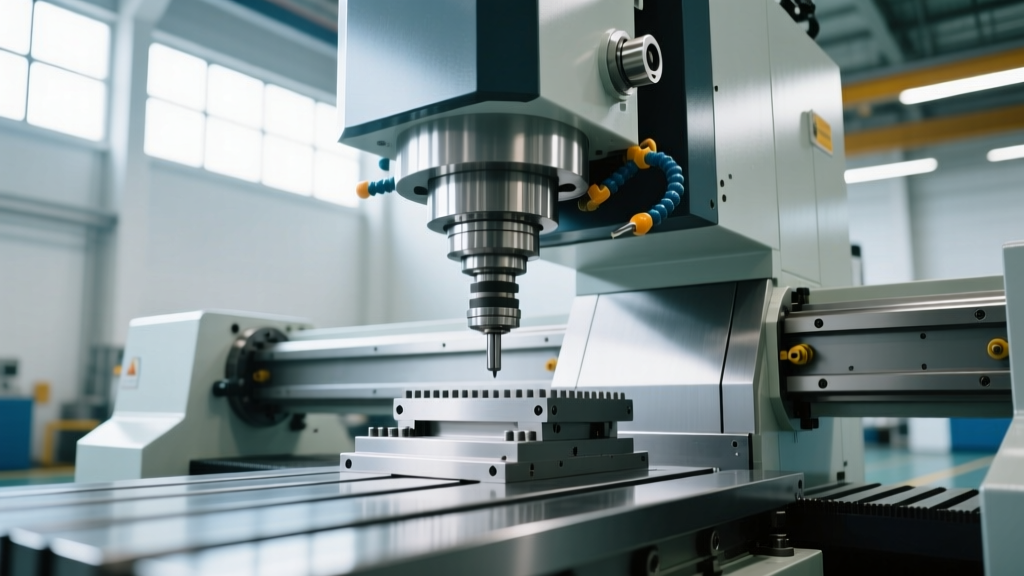
Milling CNC Machine Architecture: Core Specs & Kinematics
Explore the technical specifications of a milling CNC machine, including spindle taper kinematics, linear guideway tribology, and servo feedback loops.
The Kinematic Chain: Defining the Milling CNC Machine
A modern milling CNC machine is fundamentally a multi-body kinematic system designed to maintain sub-micron volumetric accuracy under severe dynamic cutting forces. Unlike manual mills, where the operator compensates for backlash and thermal drift in real-time, a computer numerical control system relies on rigid mechanical architecture and closed-loop feedback to execute complex toolpaths. When evaluating the technical specifications of any vertical or horizontal machining center, the performance envelope is dictated by three primary subsystems: the spindle interface, the linear motion guideways, and the servo control loop.
Critical Engineering Note: The structural loop of a milling CNC machine begins at the spindle nose, travels through the Z-axis saddle, column, bed, and linear axes, and closes at the cutting tool edge. Any compliance, thermal expansion, or vibration within this loop directly translates to part error.Spindle Taper Architecture and Torque Delivery
The spindle is the heart of the machine, but the toolholding interface dictates how effectively motor torque is transferred to the cutting edge. The choice between standard steep tapers and dual-contact interfaces fundamentally alters the machine's capability profile.
BT vs. HSK Toolholding Interfaces
Standard BT (MAS 403) tapers rely entirely on the friction of the 7:24 taper for radial stiffness and torque transmission. At high rotational speeds (above 12,000 RPM), centrifugal force causes the spindle nose to expand radially. Because the solid toolholder shank does not expand at the same rate, the taper connection loosens, resulting in a loss of Z-axis position and severe chatter.
Conversely, the HSK (Hollow Shank Taper) interface utilizes a 1:10 taper with a simultaneous face-and-taper clamping mechanism. As centrifugal force expands the spindle nose, the HSK toolholder is pulled tighter against the spindle face, maintaining rigidity. According to Sandvik Coromant's machining methodology guidelines, dual-contact interfaces are mandatory for high-speed aerospace milling where spindle speeds exceed 18,000 RPM.
| Interface | Clamping Method | Max Practical RPM | Radial Stiffness | Primary Application |
|---|---|---|---|---|
| BT40 | Pull-stud (Taper only) | 12,000 | Medium | General VMC, aluminum/steel |
| BT50 | Pull-stud (Taper only) | 8,000 | High | Heavy roughing, titanium |
| HSK-A63 | Dual-contact (Face + Taper) | 24,000+ | Very High | High-speed mold, aerospace |
Linear Motion Systems: Tribology and Damping
The linear axes determine the rapid traverse rates, positioning accuracy, and dynamic damping of the milling CNC machine. Manufacturers must choose between recirculating linear guideways and traditional cast-iron box ways, a decision that permanently defines the machine's cutting personality.
Linear Guideways (Rolling Friction)
Linear guideways utilize recirculating ball or roller bearings running on hardened steel rails. They offer a remarkably low coefficient of friction (typically μ = 0.003 to 0.005). This allows for rapid traverse rates up to 48 m/min and high acceleration (up to 1.5G) without stick-slip phenomena. However, rolling elements provide minimal dynamic damping. When subjected to heavy interrupted cuts, linear guides can transmit high-frequency vibrations directly into the machine casting, limiting the depth of cut in hard materials.
Box Ways (Sliding Friction)
Box ways rely on sliding contact between cast-iron surfaces, often coated with Turcite-B or Moglice to prevent galling. The coefficient of friction is significantly higher (μ = 0.05 to 0.08), which limits rapid traverses to roughly 20 m/min. The trade-off is massive dynamic damping. The large surface area and sliding friction absorb chatter harmonics, making box-way milling CNC machines the undisputed choice for heavy hogging in Inconel and hardened steels.
"The selection between linear guides and box ways is not about which is 'better,' but rather matching the tribological damping profile to the specific frequency of the cutting forces generated by the target workpiece material."
Servo Control and Feedback Resolution
The mechanical structure is only as accurate as the feedback loop controlling it. Modern 2026 control systems utilize absolute serial encoders rather than incremental pulse encoders, eliminating the need for homing cycles upon machine startup.
- Encoder Resolution: Standard servo motors now feature 16-million to 32-million pulse encoders per revolution. On a ball screw with a 10mm pitch, a 16-million pulse encoder yields a theoretical resolution of 0.0006 microns per pulse, far exceeding the mechanical backlash of the system.
- Ball Screw Accuracy Grades: High-end machining centers utilize C3 grade precision ground ball screws, guaranteeing a lead error of less than 8 microns per 300mm of travel. Standard production machines often use C5 grade screws (18 microns per 300mm).
- Backlash Compensation: CNC controllers map the mechanical backlash at the ball screw nut and inject a reverse-offset pulse when the axis changes direction. However, thermal growth of the ball screw during high-speed machining can alter the pitch dynamically, requiring spindle-cooled ball screws or linear glass scales for true closed-loop positioning.
Real-World Specification Analysis: Market Context
To contextualize these specifications, consider the current market landscape for vertical machining centers (VMCs). Based on current pricing and spec sheets from major OEMs like those listed on the Haas Automation vertical mill catalog, distinct tiers emerge based on kinematic priorities.
Market Tier 1: High-Production VMC (e.g., Standard 40-Taper)Target: High-volume aluminum and mild steel.
Specs: 12,000 RPM direct-drive spindle, linear guideways, 30 m/min rapids, C5 ball screws.
Approximate Cost: $75,000 - $95,000 USD.
Limitation: Lacks the damping for heavy titanium roughing; thermal drift limits tight-tolerance boring over long shifts. Market Tier 2: High-Speed / High-Precision VMC
Target: Aerospace structural components, injection molds.
Specs: 20,000+ RPM HSK-A63 spindle, hardened box ways or high-rigidity roller guideways, linear glass scale feedback, thermal compensation algorithms.
Approximate Cost: $180,000 - $250,000+ USD.
Advantage: Maintains volumetric accuracy within 5 microns despite ambient shop temperature fluctuations.
Thermal Growth and Volumetric Accuracy Standards
The ultimate test of a milling CNC machine's architecture is its volumetric accuracy under thermal load. As the spindle bearings generate heat and the ball screws stretch from friction, the machine's geometry distorts. High-end manufacturers mitigate this through symmetric column designs, spindle chiller units, and real-time thermal compensation tables embedded in the CNC controller.
Performance is verified using ISO 230 standards. Specifically, ISO 230-6 dictates the testing methods for the accuracy of speeds and interpolations, while ISO 230-3 covers thermal effects. When reviewing a machine's technical specification sheet, always look for the thermal displacement data (usually measured in microns over a 4-hour warm-up cycle) rather than just the static positioning accuracy, as thermal drift is the primary cause of scrap in high-precision milling environments.
Related reading
Compaction Tools Checklist: Daily Inspections, Density Verification, and Maintenance
How To Match Real With Machines: Bridging the Gap Between Physical Parts and CNC Milling Accuracy