CNC Lathe and Milling Machine Safety Compliance Guide
Navigate OSHA, ANSI, and ISO safety standards for your CNC lathe and milling machine. Learn guarding specs, interlock requirements, and LOTO protocols.
When outfitting a modern production cell with a CNC lathe and milling machine, safety officers and shop managers must navigate a complex web of overlapping regulatory frameworks. Machine tool accidents—ranging from catastrophic chuck ejections to entanglement in rotating spindles—carry severe human and financial costs. In 2025 and beyond, OSHA enforcement has increasingly targeted inadequate point-of-operation guarding and flawed Lockout/Tagout (LOTO) procedures in multi-axis machining environments. This guide provides actionable, engineering-grade compliance specifications to ensure your equipment meets the highest safety standards.
Core Regulatory Frameworks: OSHA, ANSI, and ISO
Compliance is not a single checklist but a hierarchy of standards. While OSHA provides the legal baseline in the United States, ANSI and ISO standards offer the engineering specifics required to actually achieve compliance. According to OSHA 1910.212 (General Requirements for All Machines), one or more methods of machine guarding shall be provided to protect the operator and other employees in the machine area from hazards such as those created by point of operation, ingoing nip points, rotating parts, flying chips, and sparks.
| Standard | Scope & Application | Key Compliance Requirement |
|---|---|---|
| OSHA 1910.212 | General Industry Machine Guarding | Mandatory physical barriers at the point of operation; secure anchoring of guards. |
| ANSI B11.8 / B11.6 | Milling Machines / Lathes | Specific spindle speed interlocks, chuck guarding, and chip management protocols. |
| ISO 16090-1 | Machine Tool Safety (Machining Centres) | Impact resistance calculations for polycarbonate enclosures based on tool mass and velocity. |
| ISO 13849-1 | Safety of Machinery - Control Systems | Performance Level (PL) rating for interlocks and light curtains (typically PL d or e). |
Physical Guarding and Impact Resistance Specifications
The most critical vulnerability on any CNC lathe and milling machine is the failure of the primary enclosure during a tool breakage or workpiece ejection event. Standard acrylic (PMMA) or PETG plastics are strictly prohibited for primary impact zones due to their brittle failure modes. Facilities must utilize abrasion-resistant polycarbonate (e.g., Lexan Margard or Makrolon AR).
Calculating Polycarbonate Thickness
Under ISO 16090 and ANSI B11 guidelines, guard thickness is dictated by the kinetic energy of the heaviest rotating component (tool, toolholder, or chuck jaw) at maximum RPM.
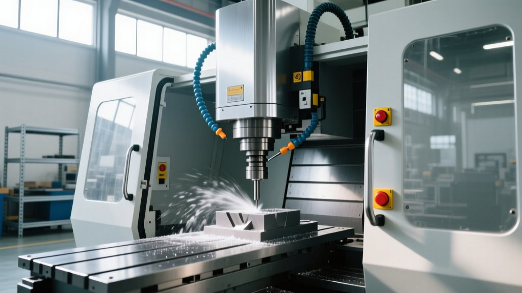
- Standard Vertical Mills (BT40/CAT40, max 12,000 RPM): Minimum 6mm (0.236") polycarbonate. Withstands approximately 120 Joules of impact energy.
- Heavy-Duty CNC Lathes (12"+ Chucks, max 4,000 RPM): Minimum 10mm to 12mm (0.39" - 0.47") polycarbonate. Chuck jaw ejections can exceed 300 Joules of kinetic energy.
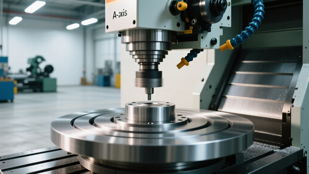
- 5-Axis Machining Centres (HSK-A100, high mass): Minimum 15mm polycarbonate, often supplemented with steel mesh backing to prevent penetration while maintaining visibility.
Polycarbonate degrades rapidly when exposed to synthetic cutting fluids, specifically those containing high concentrations of sulfur or chlorine-based EP (Extreme Pressure) additives. Inspect all enclosure windows quarterly for micro-crazing (fine spiderweb cracking). If crazing is detected, immediate replacement is required, as impact resistance drops by up to 80%.
Interlock Switches and Control System Reliability
Physical guards are useless if operators can bypass them. Modern compliance requires Category 3 or Category 4 safety architectures under ISO 13849-1. This means the safety circuit must be dual-channel with cross-monitoring. If one channel fails, the machine must halt, and the fault must be detected before the next demand on the safety system.
For sliding doors on a CNC lathe and milling machine, mechanical tongue-and-groove interlocks (like the Schmersal AZM series) are being phased out in favor of RFID-coded, non-contact safety switches (such as the Euchner MCM or SICK STR1).
"RFID-coded interlocks defeat the traditional 'zip-tie and tape' bypass methods that plague mechanical switches. Because the actuator is uniquely coded, the safety relay will not engage if a spare magnet or piece of metal is waved near the sensor, ensuring strict adherence to OSHA's anti-defeat mandates."
Guard Locking vs. Interlocking
It is vital to distinguish between a simple interlock (which cuts power when opened) and a guard locking switch. For any spindle that exhibits a coast-down time exceeding 10 seconds, or any chuck with high rotational inertia, a guard locking switch (e.g., Euchner MGB2) is legally required. This device physically locks the door shut until the spindle RPM reaches absolute zero, verified via a secondary safe-speed monitoring module.
Presence-Sensing: Light Curtains and Laser Scanners
For open-bed CNC lathes or large gantry milling machines where physical enclosure is impractical, presence-sensing devices must be deployed. Compliance with ISO 13855 dictates the exact mounting distance from the hazard zone using the safety distance formula:
ISO 13855 Safety Distance Formula: S = (K × T) + CS = Minimum distance (mm) from the detection zone to the hazard.
K = Approach speed of the human body (typically 2000 mm/s for hand approach).
T = Total machine stopping time (seconds), including light curtain response time, safety relay time, and the physical brake engagement time of the spindle motor.
C = Additional distance based on the light curtain's resolution (e.g., 850 mm for a 30mm hand-detection resolution).
If a machine's braking system takes 0.8 seconds to halt the spindle, and the light curtain (e.g., Keyence GL-R series with 25mm resolution) has a response time of 0.02 seconds, the minimum mounting distance S must be calculated precisely. Mounting the curtain too close to the chuck or spindle is a frequent and severe OSHA citation.
Coolant Mist Extraction and Respiratory Compliance
Safety compliance extends beyond mechanical hazards to occupational health. High-pressure coolant systems (70 to 150 bar) used in modern CNC milling and turning generate sub-micron aerosolized mist. OSHA's Permissible Exposure Limit (PEL) for mineral oil mist is 5 mg/m³ over an 8-hour TWA. However, NIOSH recommends a much stricter limit of 0.4 mg/m³ to prevent occupational asthma and lipoid pneumonia.
To maintain compliance and protect HVAC systems:
- Enclosure Sealing: Use labyrinth seals and negative-pressure draft gaps around the tool changer and chip conveyor exits to prevent mist escape.
- Centrifugal vs. HEPA Filtration: For water-soluble coolants, a 3-stage centrifugal collector (e.g., Filtermist) is sufficient. For neat cutting oils or high-pressure applications, a HEPA-filtered media collector (e.g., Losma or Absolent) is mandatory to capture particles smaller than 1.0 microns.
- Make-up Air: Ensure the extraction system is balanced with make-up air to prevent negative shop pressure, which can pull dust from other departments into the machining cell.
Lockout/Tagout (LOTO) and Energy Isolation
According to OSHA's Machine Guarding and LOTO guidelines, simply turning off the control panel is never sufficient for maintenance. A compliant LOTO procedure for a CNC lathe and milling machine must address all forms of stored energy:
- Electrical: Main disconnect switch must be locked in the OFF position. Verify zero voltage using a CAT III or CAT IV multimeter at the spindle drive and axis servo drives.
- Pneumatic: Many machines use air for tool clamping (drawbars) and chuck actuation. A compliant pneumatic lockout requires a manual dump valve (e.g., SMC AV series with soft-start/lockout functionality) to bleed all downstream pressure to zero, verified by a localized gauge.
- Hydraulic: Tailstocks, steady rests, and hydraulic tool clamps utilize accumulators that can store lethal pressure even when the pump is off. Maintenance protocols must include manual bleeding of hydraulic accumulators.
- Gravitational/Mechanical: Vertical Z-axes on milling machines and heavy lathe tailstocks must be mechanically blocked or supported with rated cribbing before personnel enter the envelope, as brake failure can cause uncontrolled dropping.
Common Compliance Failures and Avoidance Strategies
When auditing shops for safety compliance, safety engineers consistently find the same high-risk violations. Avoid these critical errors:
1. Defeated Door Interlocks
Operators frequently tape over mechanical limit switches to keep doors open during setup, allowing them to use dial indicators or edge finders while the spindle is live. Solution: Implement RFID-coded safety switches and enable "Safe Limited Speed" (SLS) modes via the CNC controller (e.g., FANUC Safe Zone or Siemens Safety Integrated). This allows the spindle to rotate at a maximum of 2 m/s surface speed (approx. 200 RPM on a 6" part) with the door open, rendering the bypass unnecessary while maintaining safety.
2. Inadequate Chip Conveyor Guarding
The hinge-belt chip conveyor is a massive entanglement hazard. The in-going nip point where the belt wraps around the drive sprocket must be guarded. Solution: Install fixed mesh guards (maximum 12mm aperture) over the conveyor drive motor and tail pulley, secured with tamper-resistant Torx or Allen hardware.
3. Unsecured Workholding
Using standard manual lathe chucks on CNC machines without a rotational speed limiter. Solution: Always utilize CNC-specific power chucks with centrifugal force compensation, and ensure the CNC program includes an RPM limit code (e.g., G50 S2500) that prevents the operator from overriding the maximum safe chuck speed via the spindle override dial.