3D Printed CNC Milling Machine: Technical Specs & Mechanics
Explore the technical specifications, structural mechanics, and real-world cutting limits of a 3D printed CNC milling machine for prototyping.
The Architecture of Polymer-Frame CNC Milling
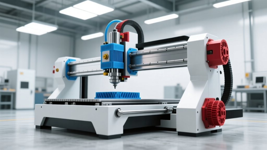
A 3D printed CNC milling machine represents a hybrid manufacturing paradigm, utilizing additive processes to create the structural chassis for subtractive machining. Unlike traditional benchtop mills that rely on cast iron or heavy aluminum extrusions, polymer-frame CNCs leverage the geometric freedom of Fused Deposition Modeling (FDM) to create custom, monocoque or semi-monocoque gantry structures. When engineered correctly, these machines can achieve repeatability within 0.05mm over a 300mm work envelope, making them highly viable for rapid prototyping, PCB isolation milling, and light-duty aluminum machining.
Critical Material Warning: Never use Polylactic Acid (PLA) for structural CNC components. PLA has a glass transition temperature of roughly 60°C. The ambient heat generated by stepper motors and spindle routers will cause PLA frames to soften, leading to catastrophic loss of dimensional accuracy and gantry sag. Always specify ABS, ASA, Polycarbonate (PC), or Carbon-Fiber reinforced polymers (ABS-CF/PETG-CF) for load-bearing printed parts.Core Technical Specifications Matrix
The performance envelope of a 3D printed CNC is dictated by its component selection. Below is a comparative matrix detailing the standard specifications for a high-performance DIY printed CNC versus a commercial entry-level router.
| Component | High-Spec 3D Printed CNC | Commercial Benchtop (e.g., Shapeoko) | Milling Impact |
|---|---|---|---|
| Frame Material | Annealed ABS / PC (100% infill) | Aluminum Extrusion (V-Slot) | Printed frames dampen high-frequency vibration better but lack the sheer mass to absorb heavy cutting forces. |
| Linear Motion (XY) | MGN12H Linear Rails + 9mm GT2 Belts | V-Wheel Carriages on Extrusions | MGN12H rails eliminate the backlash and slop inherent in V-wheel systems, crucial for climb milling. |
| Z-Axis Drive | 1204 Ball Screw (Preloaded) | ACME Lead Screw (TR8x8) | Ball screws prevent Z-axis droop when the spindle is powered off and eliminate stick-slip friction during micro-adjustments. |
| Stepper Motors | NEMA 23 (3.0 Nm holding torque) | NEMA 23 (1.2 Nm holding torque) | Higher torque prevents skipped steps during aggressive roughing passes in hard materials. |
| Controller | FluidNC (ESP32-based, 32-bit) | GRBL (8-bit Arduino) | 32-bit controllers process complex G-code arcs smoothly, preventing the micro-stutters that cause dwell marks on the workpiece. |
Kinematics and Motion Control Dynamics
Most 3D printed CNCs utilize a standard Cartesian (XYZ) gantry topology due to the ease of printing orthogonal mounting plates. However, the transition from 8-bit GRBL controllers to 32-bit architectures like FluidNC has fundamentally changed how these machines handle kinematics. FluidNC, running on an ESP32 microcontroller, supports advanced features such as closed-loop stepper integration and real-time Wi-Fi pendant control.
Managing Belt Stretch and Backlash
In belt-driven XY axes, the primary enemy of precision is hysteresis. To mitigate this in a printed frame, builders must use steel-core GT2 belts rather than standard fiberglass-core variants. Steel-core belts reduce elastic stretch by up to 80% under the 15-20 lbs of tension required to maintain tracking. Furthermore, implementing dual-motor Y-axis drives (slaved motors on independent drivers) prevents the gantry racking that occurs when a single motor drives both sides via a long connecting shaft.
Spindle Integration and Z-Axis Deflection
The Z-axis is the most critical failure point on any 3D printed CNC milling machine. The leverage exerted by a spindle motor mounted on a cantilevered Z-carriage creates significant bending moments. If the Z-axis is printed in standard PETG with 40% infill, a 1.5kW VFD spindle will induce enough deflection to snap the carriage during a 2mm depth-of-cut (DOC) pass in steel.
"When mounting a spindle to a polymer carriage, the print orientation matters as much as the material. Z-axis carriages must be printed upright so that the layer lines run vertically, aligning the polymer's tensile strength with the downward cutting forces, rather than relying on the weaker inter-layer adhesion."
For machining non-ferrous metals and plastics, a compact trim router (such as the Makita RT0702C, delivering roughly 1.25 HP and 30,000 max RPM) remains the optimal choice for printed frames. Its lightweight profile (under 4 lbs) minimizes Z-axis sag while providing sufficient RPM for small-diameter endmills. As detailed in CNC Cookbook's feeds and speeds guidelines, maintaining high surface feet per minute (SFM) is critical when machining aluminum; the high RPM of a trim router allows for proper chip evacuation even with limited machine rigidity.
Real-World Cutting Parameters for Polymer Frames
Operating a 3D printed CNC requires a conservative approach to Material Removal Rates (MRR). The lack of sheer mass means the machine cannot absorb harmonic chatter the way a 2,000-lb cast iron mill does. Below are validated starting parameters for a rigidly built, ABS-CF printed CNC equipped with a Makita trim router and a 3-flute carbide endmill.
- 6061 Aluminum: Spindle RPM: 18,000 | Feed Rate: 400 mm/min | DOC: 0.5mm | Stepover: 40% | Note: Use single-flute or specialized ZrN coated bits to prevent chip welding. Apply mist coolant to avoid thermal expansion of the printed frame.
- Delrin (POM/Acetal): Spindle RPM: 16,000 | Feed Rate: 1,200 mm/min | DOC: 2.0mm | Stepover: 50% | Note: Delrin machines beautifully on lighter frames due to low cutting resistance. Ensure chips are cleared to prevent re-welding.
- Carbon Fiber Sheet (G10/Garolite): Spindle RPM: 20,000 | Feed Rate: 800 mm/min | DOC: 1.0mm | Stepover: 30% | Note: Highly abrasive. Use solid carbide diamond-coated bits. Enclose the machine and use active HEPA extraction, as CF dust will destroy linear rail bearings and stepper motors.
- HDPE / Cutting Board Material: Spindle RPM: 14,000 | Feed Rate: 1,500 mm/min | DOC: 3.0mm | Stepover: 45% | Note: Requires sharp, highly polished flutes (O-flute) to prevent the plastic from melting and fusing back to the workpiece.
Slicing Settings for Structural CNC Components
The mechanical integrity of a 3D printed CNC milling machine is determined in the slicer. Standard aesthetic print profiles will fail under cutting loads. Use the following parameters when slicing structural joints, motor mounts, and Z-carriages:
- Wall Count (Perimeters): Minimum 6 walls (approx. 2.4mm thick with a 0.4mm nozzle). Perimeters provide the highest tensile and compressive strength in FDM printing.
- Infill Density & Pattern: 100% infill is ideal for motor mounts. For larger gantry plates, use 60% Gyroid or 3D Honeycomb. Avoid Rectilinear infill, which creates weak shear planes along the X/Y axes.
- Layer Height: 0.2mm or 0.16mm. Thinner layers increase the surface area for inter-layer diffusion, resulting in stronger Z-axis bonding.
- Extrusion Multiplier: Increase to 1.02 or 1.05 for structural parts. A slight over-extrusion ensures micro-voids between perimeters and infill are eliminated, creating a solid, machinable block of plastic.
- Post-Processing (Annealing): If printing in ABS or Nylon, bake the parts in a temperature-controlled convection oven at 90°C for 4 hours. This relieves internal print stresses and increases the heat deflection temperature, preventing the frame from warping over months of use.
Assembly Tolerances and Squaring the Gantry
Unlike machined aluminum plates, 3D printed parts are subject to thermal warping and shrinkage. You cannot rely on the printed geometry to be perfectly square. To achieve the 0.05mm tolerance required for precision milling, builders must incorporate adjustable eccentric nuts on the linear rail carriages. By loosening the rail mounting bolts and using a dial indicator mounted to the spindle, the rails can be micro-adjusted until they are perfectly parallel to the travel axis. For comprehensive CAM setup and toolpath generation to match your machine's exact rigidity limits, refer to Autodesk's CNC machining basics to optimize your adaptive clearing strategies, which drastically reduce lateral cutting forces on polymer frames.