Haas UMC-750 CNC 5 Axis Milling Machine Operator Training Guide
Master the Haas UMC-750 cnc 5 axis milling machine with expert operator training on RTCP calibration, singularity avoidance, and inverse time feedrates.
Trunnion Kinematics and the WCS Pivot Point
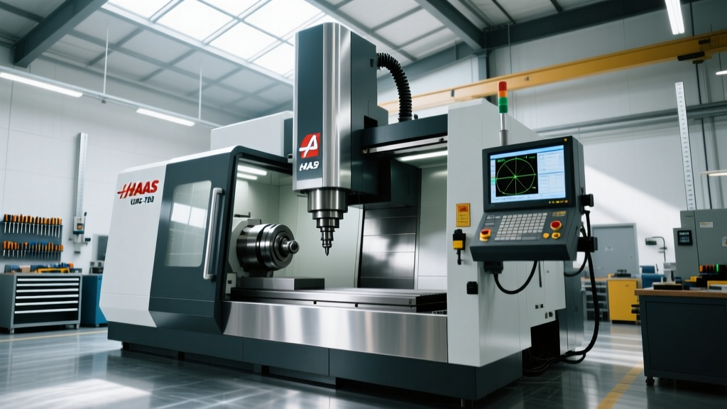
Transitioning from a standard 3-axis vertical machining center to a cnc 5 axis milling machine requires a fundamental shift in spatial reasoning and G-code comprehension. For this training guide, we will use the Haas UMC-750 as our benchmark platform. Priced around $235,000 fully equipped with probing and a chip conveyor, the UMC-750 utilizes a trunnion-style table with a B-axis (tilt, -35° to +120°) and a C-axis (rotation, 360°).
The most critical concept for new 5-axis operators is the Work Coordinate System (WCS) placement. On a trunnion table, the WCS Z-zero point must be established precisely at the center of rotation (the platter pivot point). If the WCS is placed on the top of the part instead of the rotational center, the control's rotary compensation algorithms will calculate incorrect linear moves during simultaneous machining, resulting in gouged parts or catastrophic collisions.
Operator Tip: Always use a calibrated 1-inch probing sphere mounted to the table to set your rotational center. On the Haas NGC control, run the 'Set Rotational Center' macro before establishing your part G54 offsets. This ensures the machine's internal kinematic map aligns perfectly with the physical platter.Mastering RTCP (G234) and Tool Length Calibration
Rotary Tool Center Point Control (RTCP), activated via G234 on Haas machines (often called TCPC or Tool Center Point Control), allows the programmer to output toolpath coordinates based on the part's tilted WCS rather than the machine's home position. When G234 is active, the control automatically calculates the necessary B and C axis movements to keep the tool tip exactly on the programmed XYZ coordinate.
Because the control is doing the math, tool length measurement accuracy is non-negotiable. In 3-axis machining, a tool length error of 0.001" simply shifts the Z-axis. In 5-axis RTCP machining, a 0.001" tool length error is magnified by the sine of the tilt angle. At a 90-degree B-axis tilt, a 0.002" tool length discrepancy will result in a 0.002" lateral shift of the tool tip, destroying tight-tolerance aerospace contours.
Probing System Comparison for 5-Axis Setup
| Probing System | Repeatability (2 Sigma) | Best Application | Setup Time Impact |
|---|---|---|---|
| Haas WIPS (Wireless) | ± 0.0001" (2.5 µm) | Standard aluminum/steel 5-axis parts, daily WCS setting | Low (Integrated into NGC VPS) |
| Renishaw OMP60 | ± 0.00004" (1.0 µm) | Titanium/Inconel aerospace contours, tight RTCP tolerances | Medium (Requires custom macro calls) |
| Manual Tool Setter | ± 0.0005" (12.7 µm) | Roughing only; Never use for 5-axis finishing | High (Prone to human error) |
Navigating the C-Axis Singularity
A 'singularity' occurs when the tool centerline aligns perfectly with the C-axis center of rotation (i.e., when the B-axis is at exactly 0°). In this position, the C-axis rotational velocity required to maintain a specific tool vector approaches infinity. If the CAM system commands a slight tool vector change while B is at 0°, the C-axis will violently spin hundreds of degrees to compensate, leaving severe dwell marks on the part surface or triggering a servo lag alarm.
"The golden rule of 5-axis CAM programming is to avoid the B-zero singularity entirely. Programmers should utilize 'Tilt Tool Axis' features in software like Mastercam to maintain a minimum 3° to 5° B-axis lead angle during contouring. This forces the C-axis to move at a predictable, manageable velocity, ensuring a flawless surface finish."
— Advanced Multi-Axis Machining Guidelines, Sandvik Coromant
Inverse Time Feedrates (G93) Explained
Standard feedrate programming (G94 - Inches Per Minute) fails in simultaneous 5-axis machining. Because the rotary axes move in degrees and the linear axes move in inches, the control cannot accurately blend the movements to maintain a constant tool-tip speed. If you program F50, the tool tip might move at 50 IPM, but the rotary axes could be starved for speed, causing the tool to dwell and burnish the material.
Operators must use G93 (Inverse Time Feedrate). In G93, the F-word does not represent speed; it represents the time it takes to complete the specific block of code. The formula is:
F = 1 / Time (in minutes)
If a specific 5-axis move should take 2 seconds (0.0333 minutes) to complete, the programmed feedrate is F30.0 (1 / 0.0333). Modern CAM software calculates these G93 values automatically for every line of code, ensuring perfect synchronization between the XYZ linear slides and the BC rotary table.
Thermal Stabilization and Daily Warm-Up
The 40-taper inline direct-drive spindle on the UMC-750 is highly responsive but susceptible to thermal growth. During the first 45 minutes of operation, the spindle housing will expand, shifting the Z-axis by up to 0.0008" and the X/Y axes by 0.0004". Running tight-tolerance 5-axis parts cold will result in out-of-tolerance scrap.
The 12-Minute 5-Axis Warm-Up Routine
- Minutes 0-3: Run spindle at 2,000 RPM with no axis movement to distribute bearing grease.
- Minutes 3-6: Increase spindle to 6,000 RPM. Command rapid X, Y, and Z traversals across 50% of the machine envelope.
- Minutes 6-9: Increase spindle to 10,000 RPM. Command B-axis tilts from -30° to +90° and C-axis full 360° rotations.
- Minutes 9-12: Bring spindle to 12,000 RPM (or max cutting speed). Run a circular interpolation test cut in the air or on scrap to stabilize thermal equilibrium.
Troubleshooting 5-Axis Surface Finish Defects
Even with perfect RTCP calibration, operators frequently encounter surface anomalies unique to multi-axis cutting. Use this diagnostic matrix to identify and resolve common 5-axis milling defects.
| Defect Symptom | Root Cause | Operator / CAM Fix |
|---|---|---|
| Chatter marks on deep, tilted walls | Standard end mill stickout exceeds 5xD, causing harmonic deflection during B-axis tilt. | Switch to a tapered neck end mill (e.g., Harvey Tool 5-Axis Reach series) to maintain rigidity while clearing the trunnion platter. |
| Dwell marks / burnishing at contour start/stop | C-axis servo lag during direction reversal at low feedrates. | Increase G93 inverse time feedrate values, or apply a 3° B-axis lead angle to keep the C-axis in continuous motion. |
| Stepped surface finish (cusp marks) | Using flat bottom end mills for 5-axis swarf machining without proper tool vector alignment. | Switch to a bull-nose (corner radius) end mill and ensure the CAM tool axis is set to 'Normal to Surface' for swarf cuts. |
| Tool breakage during plunge on tilted surfaces | Engaging the full diameter of the tool simultaneously on an angled face. | Utilize helical ramping or 5-axis Z-level plunge milling with a lead angle to gradually engage the cutting flutes. |
Operating a cnc 5 axis milling machine is an exercise in precision preparation. By rigorously controlling your WCS pivot points, validating tool lengths with high-accuracy probing, and respecting the kinematic limitations of the trunnion table, operators can unlock the full geometric freedom and profitability of 5-axis manufacturing.