Troubleshooting Surface Defects on CNC Machined Metal Parts
Diagnose and repair surface finish defects on CNC machined metal parts. Expert fixes for chatter, BUE, and work hardening in aluminum, steel, and titanium.
Surface finish defects on CNC machined metal parts are rarely random; they are physical manifestations of thermal, mechanical, or harmonic imbalances in the cutting zone. When a high-value aerospace titanium bulkhead shows micro-chatter or a batch of 6061-T6 aluminum valve bodies exhibits Built-Up Edge (BUE), scrapping the lot is not the only option. This guide provides a metallurgical and mechanical troubleshooting framework to diagnose in-process anomalies and execute post-machining repairs to salvage critical components.
Diagnostic Matrix: Identifying Surface Anomalies
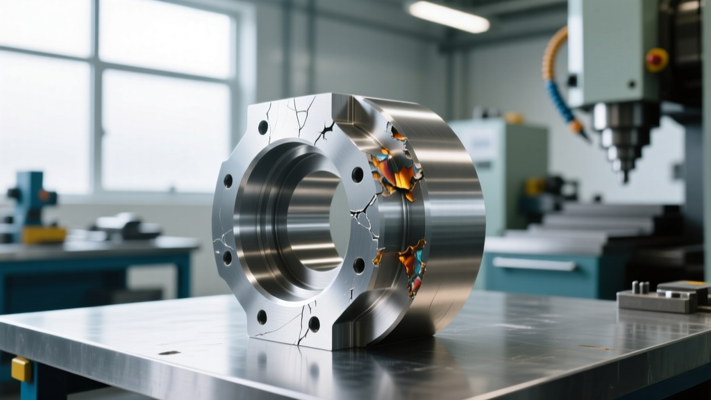
Before altering feeds, speeds, or toolpaths, correctly identify the visual signature of the defect. Misdiagnosing chatter as tool wear will lead to catastrophic scrap rates.
| Visual Symptom | Primary Material | Root Cause | Immediate Machine Fix | Post-Machining Repair |
|---|---|---|---|---|
| Smeared, shiny patches | Aluminum 6061-T6 | Built-Up Edge (BUE) / Low SFM | Increase speed to >1200 SFM; use ZrN coating | 120-grit glass bead blasting at 40 PSI |
| Evenly spaced regenerative ridges | Titanium Ti-6Al-4V | Harmonic chatter / Tool deflection | Reduce RDOC to 5%; use dynamic milling | Abrasive Flow Machining (AFM) or manual blending |
| Tear-outs and galling | 304/316 Stainless | Work hardening / Rubbing | Increase feed to maintain 0.003" chip thickness | Electropolishing or passivation |
| Micro-pitting / cratering | Hardened Steels (>45 HRC) | Thermal shock / Coolant failure | Switch to AlCrN coating; use air blast | Superfinishing / honing |
Case 1: Built-Up Edge (BUE) in Aluminum 6061-T6
Built-Up Edge occurs when workpiece material pressure-welds to the carbide cutting edge, eventually breaking off and tearing the newly machined surface. In 6061-T6 aluminum, BUE typically forms when cutting speeds drop below 800 Surface Feet per Minute (SFM) or when using standard TiAlN coatings that chemically react with aluminum at high temperatures.
The Metallurgical Fix
To eliminate BUE, you must outrun the welding threshold. Increase cutting speeds to 1,200–1,500 SFM. More importantly, transition to uncoated micro-grain carbide or ZrN (Zirconium Nitride) coated end mills. ZrN provides an exceptionally low coefficient of friction (approximately 0.25) and high lubricity, preventing aluminum adhesion. According to technical data from the Harvey Tool In The Loupe technical library, maintaining a high rake angle (35° to 45°) combined with a polished flute surface is mandatory for chip evacuation in sticky aerospace aluminum alloys.
Salvaging BUE-Damaged Parts
If BUE has already caused smearing on finished parts, do not attempt to re-cut the surface, as this will alter critical dimensional tolerances. Instead, use a media blasting cabinet with 120-grit glass bead at 40 PSI. This will strip the smeared aluminum and restore a uniform 32-63 Ra microinch finish without removing more than 0.0005 inches of base material.
Case 2: Chatter and Harmonic Deflection in Titanium Ti-6Al-4V
Titanium's low modulus of elasticity makes it highly susceptible to spring-back and regenerative chatter. Chatter leaves visible, evenly spaced marks that severely compromise fatigue life in aerospace structures. This is usually caused by an improper Length-to-Diameter (L:D) ratio or excessive radial engagement.
Stabilizing the Cut Zone
Chatter in titanium is mitigated by shifting from conventional slotting to dynamic (trochoidal) milling. Reduce the radial depth of cut (RDOC) to 5-10% of the tool diameter while maximizing the axial depth of cut (ADOC). Ensure tool overhang maintains an L:D ratio strictly below 4:1. For tooling, utilize AlCrN (Aluminum Chromium Nitride) coatings. Unlike TiAlN, AlCrN resists thermal cratering and oxidation up to 1,100°C, which is critical given titanium's poor thermal conductivity. The Sandvik Coromant Milling Knowledge Hub emphasizes that maintaining a constant tool engagement angle is the most effective way to dampen harmonic vibrations in low-rigidity setups.
Warning: Coolant Pressure in TitaniumStandard flood coolant (300 PSI) is insufficient for deep cavity milling in Ti-6Al-4V. The chips will weld to the flutes, causing tool fracture. You must use through-tool coolant at a minimum of 1,000 PSI to mechanically break the chip and evacuate it from the cut zone before it can recut and mar the surface finish.
Salvaging Chatter-Marked Components
For minor chatter marks on non-sealing, non-bearing surfaces, manual blending is the most cost-effective repair. Use 3M Scotch-Brite 7447 (maroon) pads, stroking strictly in the direction of the primary toolpath. Verify the repair using a Mitutoyo SJ-210 profilometer to ensure the surface roughness (Ra) remains below the engineering print requirement (typically 125 µin for general aerospace structures).
Case 3: Work Hardening and Smearing in 304 Stainless Steel
Austenitic stainless steels like 304 and 316 possess high ductility and a strong tendency to work-harden. If the CNC feed rate is too conservative, the cutting edge rubs the surface instead of shearing it. This friction induces a hard martensitic layer on the surface (spiking local hardness up to 60 HRC) that will instantly destroy subsequent tool passes and leave a torn, galled finish.
Enforcing Minimum Chip Thickness
The fix is counterintuitive: you must feed the tool more aggressively. Maintain a strict minimum chip thickness. For a standard 1/2-inch carbide end mill, never drop below 0.003 inches per tooth (IPT). If your machine's spindle cannot handle the torque at the required feed rate, reduce the axial depth of cut to compensate, but never sacrifice the feed per tooth. As noted in Modern Machine Shop's machining techniques archive, ensuring the tool cuts entirely below the previously work-hardened layer is the only way to achieve a consistent 63 Ra finish in austenitic stainless alloys.
Advanced Post-Machining Repair Protocols
When CNC machined metal parts fail visual or profilometer inspection, advanced secondary operations can salvage components that would otherwise cost thousands of dollars in raw material and machine time.
1. Abrasive Flow Machining (AFM)
AFM is the premier repair method for internal passages and complex geometries where manual blending is impossible. A semi-solid polymer media laden with silicon carbide or diamond abrasives is extruded through the part under high pressure (up to 3,000 PSI).
Application: Removing micro-chatter from internal hydraulic valve bores.
Parameters: Use a medium-viscosity media with 80-grit SiC. Cycle time is typically 45-90 seconds per part, removing 0.001" to 0.003" of material uniformly while compressing the surface peaks to improve fatigue resistance.
2. Electropolishing for Stainless Alloys
If 304 or 316 stainless parts exhibit micro-tearing or embedded free iron from previous machining operations, electropolishing is the definitive repair. The part is submerged in a temperature-controlled phosphoric-sulfuric acid bath (140°F - 160°F) and subjected to a DC current. This process removes the damaged, work-hardened surface layer at the atomic level, leaving a pristine, passivated, and highly corrosion-resistant finish that mechanical abrasion cannot achieve.
The Scrap vs. Salvage Decision Framework
Before initiating any repair protocol on CNC machined metal parts, run the component through this tolerance stack-up check:
- Dimensional Margin: Will the repair process (e.g., AFM, blasting) remove more than 10% of the remaining geometric tolerance? If yes, scrap the part.
- Fatigue Criticality: Is the part subjected to high-cycle fatigue (e.g., landing gear components)? Manual blending can introduce stress concentrators if not performed perfectly. Default to AFM or superfinishing.
- Cost-Benefit Ratio: If the raw material and prior machining cost exceeds $800, secondary salvage operations (typically $40-$150 per batch) are financially justified.
By understanding the metallurgical triggers of surface defects and deploying targeted secondary repair processes, manufacturers can drastically reduce scrap rates and maintain strict quality control on complex metal components.