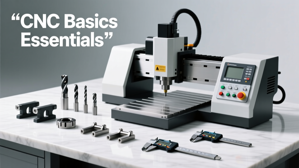
Schedules CNC Basics Essentials: Understanding Pipe, Tube, and Structural Material Specifications for Precision Machining
A practical, field-tested reference for CNC machinists, engineers, and procurement specialists on interpreting ASTM, ASME, and ANSI schedules—covering wall thickness standards, material grades, tolerances, and real-world implications for milling, turning, and fabrication of carbon steel, stainless, aluminum, and copper alloys.
What 'Schedule' Really Means in CNC Manufacturing
In CNC machining, the term 'schedule' is not a production timeline—it's a standardized designation for wall thickness in pipes, tubes, and structural hollow sections. Misinterpreting schedule numbers causes costly scrap, tool failure, and assembly mismatches. For example, a 2-inch nominal pipe size (NPS) with Schedule 40 has a wall thickness of 0.154 inches per ASTM A53, while Schedule 80 at the same NPS measures 0.218 inches—a 41% increase that directly affects rigidity, weight, coolant flow, and toolpath depth of cut. Schedules originated in early 20th-century piping standards to simplify specification without listing dimensions repeatedly. Today, they remain embedded in ISO 4200, ASTM A500 (structural tubing), ASTM A312 (stainless pipe), and ASME B36.10M/B36.19M—the foundational references used by Haas, DMG Mori, Okuma, and Mazak programming teams worldwide.
How Schedules Map to Actual Dimensions—and Why It Matters
Unlike metric tube standards (e.g., EN 10219), which specify exact outer diameter (OD) and wall thickness, North American pipe schedules rely on nominal pipe size (NPS) and a dimensionless number. NPS is loosely related to ID but diverges significantly above NPS 14. For instance, an NPS 6 pipe has an OD of 6.625 inches regardless of schedule—but its ID changes dramatically: Schedule 10 = 6.302 inches ID; Schedule 40 = 6.065 inches ID; Schedule 160 = 5.550 inches ID. That’s a 773-mil reduction in internal clearance between Schedule 10 and 160—critical when machining internal features like threaded ports or hydraulic passages on a Haas ST-30Y lathe.
ASTM vs. ASME: Key Standard Differences
ASTM standards govern material composition and mechanical properties, while ASME B31.x codes dictate pressure design rules. For CNC shops, ASTM A106 Grade B (seamless carbon steel pipe, tensile strength 60 ksi min) and ASTM A312 TP304 (austenitic stainless, yield strength 30 ksi min, elongation ≥35%) are among the top five most ordered materials for turned components. ASME B36.10M covers carbon and alloy steel, whereas B36.19M handles stainless. Crucially, ASME does not define schedules—it adopts ASTM’s dimensional tables. Confusion arises when quoting parts: a job spec calling out "2" SCH 80 SS316" must reference ASTM A312 Table A1.1, where it shows OD = 2.375", wall = 0.218", and weight = 5.79 lb/ft—not the carbon steel values in B36.10M.
Common Schedule Pitfalls in CNC Programming
One frequent error occurs during CAM setup: assuming uniform wall thickness across bends or fittings. Seamless pipe maintains schedule integrity through bending, but welded pipe may thin at the extrados. When roughing a flange face on a 4" Schedule 80 ASTM A106B pipe blank using a Sandvik CoroMill 390 cutter, feed rates must drop 12–15% entering the heat-affected zone near weld seams—even if the part drawing omits seam location notes. Another trap: specifying "Schedule 40" without stating the standard. ASTM A53 Schedule 40 differs from ASTM A500 Grade C Schedule 40 in both chemistry and tolerance bands—A500 permits ±10% wall variation versus ±12.5% for A53, affecting first-article inspection pass rates.
Schedule Tolerances: Where Real-World Variability Hits Your Tool Life
ASTM standards define permissible wall thickness deviations—not as fixed values, but as percentages relative to nominal wall. For hot-finished carbon steel pipe per ASTM A500, wall tolerance is ±10% for walls ≤0.156", and ±9% for walls >0.156". So a 3" Schedule 40 A500 tube (nominal wall 0.216") can legally range from 0.197" to 0.235"—a 38-mil swing. On a vertical machining center like the Makino V55, this variability forces conservative depth-of-cut limits. Running a full-slot mill at 0.200" DOC risks chatter or breakage if the local wall drops below 0.197". Shops using Mitutoyo height gages for incoming inspection routinely log 3–5 spot checks per 20-ft length to validate compliance before fixturing.
Material-Specific Schedule Behavior Under Machining Stress
Aluminum structural tubing (ASTM B221) behaves differently than steel under identical schedule labels. A 3" × 2" rectangular tube, Schedule 40, in 6061-T6 has nominal wall 0.216" but yields at just 35 ksi—versus 58 ksi for A500 Grade C. This lower yield strength increases deflection during 3+ axis contouring. At 8,000 rpm with a Kennametal KSR end mill, radial tool deflection in Al exceeds 0.003" at 0.150" axial DOC—requiring adaptive toolpaths or reduced stepovers. Conversely, duplex stainless 2205 (ASTM A790) in Schedule 10 shows minimal thermal expansion during long-turn operations but demands 30% lower surface speeds (SFM) than 304 due to higher hardness (290 HB vs. 200 HB).
CNC Fixture Design Implications of Schedule Selection
Fixture engineers must account for schedule-driven stiffness differences. A 6" OD × 0.250" wall (Schedule 80 equivalent) A106B pipe deflects 0.0021" under 500 lbf clamping force over a 12" span—measured via FaroArm on a ProtoTRAK SMX mill. But the same OD at Schedule 40 (0.280" wall) deflects only 0.0013". That 0.0008" difference seems trivial until you're holding ±0.0015" positional tolerance on drilled flange holes. Many Tier-1 aerospace suppliers—including those machining manifolds for Pratt & Whitney F135 engines—mandate schedule verification via ultrasonic thickness (UT) scanning before fixture loading. UT probes from Olympus EPOCH 650 detect variations down to ±0.001" and flag outliers exceeding ASTM A53’s ±12.5% wall tolerance.
Interpreting Schedule Data Tables Across Standards
Manufacturers publish schedule data in dense tabular form. Below is a comparison of critical dimensions for common NPS sizes across three major standards—essential for quoting and process planning:
| NPS | Schedule | OD (in) | Wall (in) | ID (in) | Std Ref | Typical Use Case |
|---|---|---|---|---|---|---|
| 2 | 40 | 2.375 | 0.154 | 2.067 | ASTM A53 | General-purpose hydraulic lines |
| 2 | 80 | 2.375 | 0.218 | 1.939 | ASTM A53 | High-pressure steam manifolds |
| 4 | 40 | 4.500 | 0.237 | 4.026 | ASTM A500 Gr.C | Structural chassis frames |
| 4 | 80 | 4.500 | 0.337 | 3.826 | ASTM A500 Gr.C | Heavy-duty equipment booms |
| 6 | 160 | 6.625 | 0.432 | 5.761 | ASME B36.10M | Oil & gas wellhead components |
When to Specify Exact Dimensions Instead of Schedule
While schedules streamline communication, they’re inadequate for precision CNC applications demanding tight geometric control. Consider these four scenarios where explicit OD, ID, and wall callouts are mandatory:
- Thin-wall turning: Parts requiring wall thickness ≤0.065" (e.g., titanium aerospace bleed air tubes) exceed the resolution of standard schedule definitions. ASTM B338 specifies exact wall tolerances of ±0.003"—not a schedule number.
- Multi-axis contouring of non-circular sections: Rectangular or oval tubing per ASTM A500 doesn’t map cleanly to round-pipe schedules. A 5" × 3" × 0.188" tube has no ‘Schedule 40’ equivalent—specify all three dimensions.
- Metric-based global supply chains: European customers use EN 10219 (e.g., “CHS 114.3 × 5.0 mm”) rather than NPS/Schedule. Converting introduces rounding errors: 5.0 mm = 0.1969", but Schedule 40 for NPS 4" = 0.237"—a 40-mil discrepancy.
- Heat-treated post-machining: After solution annealing 316 stainless tubing, wall distortion averages 0.004–0.008" radially. Specifying final ground dimensions post-heat-treat avoids scrap due to schedule drift.
Real-World Schedule Verification Protocols in Production Shops
Leading CNC contract manufacturers enforce three-tier verification:
- Level 1 – Incoming Inspection: Every bundle receives OD measurement (Mitutoyo 500-196-30) and two-point wall check (Olympus CL5 UT gauge) at three locations along length. Nonconforming lots are quarantined immediately.
- Level 2 – In-Process Validation: After rough turning on a Doosan Puma 3100SY, operators verify wall remaining with Starrett 789B tube micrometer—calibrated daily against NIST-traceable masters.
- Level 3 – Final Audit: CMM inspection (Hexagon Global S 12.15.10) scans full circumference at 1° intervals, generating deviation heatmaps aligned to GD&T callouts per ASME Y14.5–2018.
This protocol reduced first-pass scrap by 22% at a Tier-1 medical device supplier machining 17-4PH pump housings—where Schedule 10 (0.133" wall) was misread as Schedule 5S (0.095" wall) on initial PO review.
Material cost also scales nonlinearly with schedule. For 304 stainless pipe, Schedule 40 costs $4.80/lb; Schedule 80 jumps to $6.15/lb (+28%); Schedule 160 reaches $8.90/lb (+85%). Yet machining time increases only ~18% from Sch40 to Sch80 due to higher rigidity enabling faster feeds. The ROI favors higher schedules when part life, pressure rating, or fatigue resistance outweigh raw material premium—as proven in Parker Hannifin’s hydraulic manifold redesign, which shifted from Sch40 to Sch80 and extended service life from 8,500 to 22,000 operating hours.
Thermal conductivity differences further impact CNC decisions. Copper pipe (ASTM B42) in Schedule 40 has thermal conductivity of 220 BTU/hr·ft·°F—more than 5× that of 304 stainless. During high-MRR milling on a Fadal VMC-4020, copper’s rapid heat dissipation allows 25% higher feed rates but demands rigid toolholding: ER-25 collets show measurable runout growth beyond 0.0008" at 12,000 rpm, causing premature insert chipping in Kennametal KCU25 carbide.
Surface finish requirements interact critically with schedule. A Schedule 10 3" pipe (0.113" wall) cannot sustain a 16 Ra finish after turning without support mandrels—the thin wall vibrates at harmonics matching spindle frequencies. In contrast, Schedule 160 (0.375" wall) achieves 8 Ra consistently using Sandvik CoroTurn DL toolholders with damping cartridges. This isn’t theoretical: Boeing’s 787 landing gear bracket specs demand 12 Ra on critical bearing surfaces—only achievable on Schedule 80+ 4340 steel forgings, never on lighter schedules.
Thread engagement depth is another hidden variable. For NPT threads cut into Schedule 40 pipe, minimum thread engagement is 5.5 threads per inch (TPI) per ASME B1.20.1. But Schedule 80’s thicker wall permits deeper thread roots—increasing pull-out strength by 33% in tensile testing per ASTM F606. That’s why API 6A wellhead valves mandate Schedule 120 or heavier for critical sealing zones.
Finally, consider corrosion allowance. Offshore oil platforms specify ASTM A106B Schedule 120 not for pressure alone—but to retain 0.125" wall after 25 years of seawater exposure. CNC programmers must subtract that allowance before calculating final cut depths. Failure to do so caused a documented $340,000 rework event at a Gulf Coast valve fabricator when 12" Schedule 120 bodies were machined to nominal wall instead of design-minus-corrosion.
Understanding schedules isn’t about memorizing tables—it’s recognizing how a dimensionless label propagates through material selection, toolpath generation, fixturing, inspection, and lifecycle performance. Whether you’re running a Haas VF-2SS or programming a multi-tasking Nakamura-Tome WTY-150, treating schedule as a starting point—not a specification endpoint—prevents avoidable failures and unlocks repeatable precision.
For immediate application, cross-reference your next job’s schedule callout against ASTM A53, A106, A312, or A500—never assume equivalence across material families. And always verify actual wall thickness before loading into a vise or chuck: that 0.005" variance could be the difference between hitting ±0.0005" true position or scrapping $1,200 of Inconel 625.
Modern CNC demands dimensional literacy—not just G-code fluency. When your programmer asks, 'Which schedule?', the right answer starts with the standard, the material grade, and the measured wall—not just a number.
Schedules aren’t legacy artifacts. They’re living specifications that shape every chip removed, every clamp tightened, and every component that meets its operational lifespan. Respect them, verify them, and engineer around their real-world behavior—not the textbook ideal.
The next time you see 'Sch 40' on a print, don’t just input the number. Pull ASTM A53 Table A1. Confirm the OD matches your stock. Check if your coolant delivery system can reach the ID without obstruction. Validate wall consistency across the billet. Then—and only then—hit cycle start.
No two Schedule 40 pipes behave identically under CNC load. But with disciplined interpretation and verification, you turn dimensional ambiguity into predictable, profitable output.