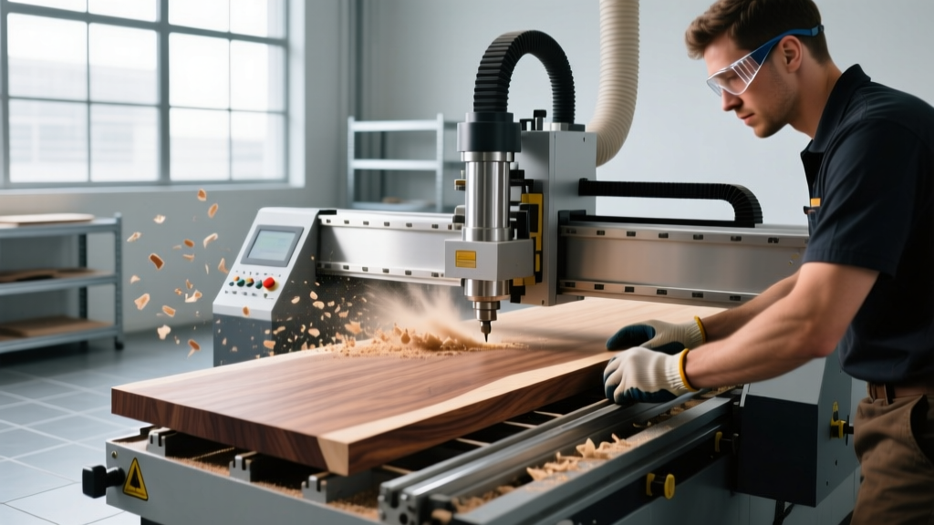
CNC Cutting Wood Machine: Operator Training and Best Practices
Train operators on CNC cutting wood machine best practices. Learn feed rates, tooling, vacuum workholding, and dust extraction for modern shops.
The True Cost of Untrained CNC Wood Operators
A single crash on a high-production CNC cutting wood machine can destroy a $120 solid carbide compression bit, damage the spindle bearings, and halt production for hours. In modern custom cabinet and millwork shops running 24,000 RPM spindles, the margin for error is measured in thousandths of an inch. Operator training cannot be limited to simply loading G-code and pressing the green cycle start button. True proficiency requires a deep understanding of material shear mechanics, vacuum pod dynamics, and toolpath verification. This guide provides shop managers and lead machinists with a technical framework for training operators on woodworking CNC routers.
The First 30 Days: Operator Competency Checklist
- Week 1: Machine geometry, homing sequences, and emergency stop (E-stop) circuit testing.
- Week 2: Spoilboard surfacing, vacuum pod placement, and part registration against stops.
- Week 3: Tool length measurement (Z-axis probing), tool radius compensation, and collet maintenance.
- Week 4: Dry-run verification, single-block execution, and feed-rate override management.
Tooling Mechanics: Matching the Bit to the Shear Line
The most common mistake new operators make is selecting the wrong router bit profile for the material thickness, resulting in severe edge tear-out. Wood machining relies heavily on specialized shear angles and flute geometries to evacuate chips without splintering the melamine or veneer surfaces.
Compression Bits: The Sweet Spot Rule
Compression bits feature an up-cut geometry at the tip and a down-cut geometry at the top. The up-cut section pulls chips away from the bottom laminate, while the down-cut section pushes chips away from the top laminate. The transition point is called the shear line.
Critical Training Point: The shear line must be positioned entirely inside the material thickness. If you are cutting 1/2-inch (12.7mm) plywood, you must use a compression bit with an up-cut length of 3/8-inch or less. If an operator uses a standard 1/2-inch compression bit (which typically has a 5/8-inch up-cut length) on 1/2-inch material, the up-cut flutes will extend above the top surface, violently blowing out the top veneer.
Collet Maintenance and Runout
Tool life is directly tied to spindle runout. Operators must be trained to clean collets and collet nuts with a brass brush and compressed air every single shift. A buildup of 0.002 inches of wood pitch inside an ER32 collet will cause the bit to deflect at 18,000 RPM, leading to chipped carbide edges and a poor surface finish. Replace collets every 6 to 12 months depending on usage intensity.
Material-Specific Feed and Speed Matrix
Feeding a CNC cutting wood machine too slowly causes friction, generating enough heat to burn the wood resins and melt plastic laminates. Feeding too fast causes tool deflection and catastrophic bit breakage. Operators must memorize or have immediate access to the following baseline parameters for standard 1/2-inch shank solid carbide tooling.
| Material | Bit Profile | RPM | Feed Rate (IPM) | Chipload |
|---|---|---|---|---|
| 3/4" MDF (Melamine) | Compression (3 Flute) | 18,000 | 450 | 0.0125" |
| 3/4" Baltic Birch Ply | Compression (2 Flute) | 18,000 | 350 | 0.0097" |
| 1" Hard Maple | Up-Cut (2 Flute) | 16,000 | 220 | 0.0068" |
| 1/2" Acrylic / Solid Surface | O-Flute (Single Up-Cut) | 16,000 | 150 | 0.0093" |
Note: Chipload is calculated as Feed Rate / (RPM x Number of Flutes). Operators should be trained to calculate chipload on the fly when testing new materials to ensure the bit is taking a thick enough chip to carry heat away from the cutting edge.
Vacuum Workholding and Spoilboard Management
On flat-table CNC cutting wood machines, vacuum hold-down is the standard. However, operators frequently misunderstand how vacuum pressure interacts with the spoilboard and the part.
Spoilboard Surfacing Tolerances
The spoilboard (typically 3/4-inch low-density MDF) must be fly-cut or surfaced regularly to maintain a perfectly flat, porous plane. Operators must be trained to leave exactly 0.010 to 0.015 inches of material after surfacing. If the spoilboard is machined too thin, the vacuum will bleed out the edges of the table rather than pulling through the top surface, resulting in parts shifting during aggressive profiling passes.
Pod Placement and Gasketing
When using raised vacuum pods for edge-banding or hardware boring operations, operators must ensure the rubber gaskets are seated perfectly in the pod grooves. A gap of just 1/16-inch in the gasket seal will drop the vacuum pressure from 80 kPa to below the 60 kPa threshold required to hold a part against lateral cutting forces. Train operators to use a digital manometer to verify pod pressure before starting a nested batch run.
Warning: Mechanical Clamp Interference
When combining vacuum hold-down with mechanical toggle clamps for small, narrow parts, operators must program a 3D toolpath boundary that respects the Z-height of the clamps. A common crash occurs when the Z-axis safe zone is set to 0.5 inches, but the toggle clamp extends 1.25 inches above the material surface. Always map clamp locations as 'keep-out' zones in your nesting software (e.g., Cabinet Vision, Microvellum) and verify Z-clearance planes manually.
Real-World Troubleshooting Matrix
Operators must be trained to diagnose cut quality issues by examining the chips and the finished edge, rather than blindly adjusting feed rates. Use this decision matrix on the shop floor.
- Symptom: Top melamine edge is chipped; bottom edge is clean.
Cause: Down-cut flutes are dull, or the bit is pulling too deep (shear line is below the material).
Fix: Index the bit up in the collet by 1/16-inch or replace the tool. Check Z-axis zeroing. - Symptom: Burn marks on the cut edge of solid wood.
Cause: Feed rate is too slow, causing the bit to rub instead of shear, or the dust collection shoe is clogged, recirculating hot chips.
Fix: Increase feed rate by 15% and verify dust extraction velocity. - Symptom: Dimensional inaccuracy (parts are 0.015" undersized).
Cause: Tool deflection due to excessive depth of cut or worn spindle bearings.
Fix: Reduce depth of cut to 60% of the tool diameter per pass. If problem persists, run a dial indicator test on the spindle taper.
Dust Collection and Combustible Hazard Protocols
Wood dust is not just a nuisance; it is a severe respiratory and combustible hazard. Modern CNC cutting wood machines generate massive volumes of fine particulate, particularly when routing MDF. Operators must understand the relationship between the machine's dust hood and the facility's extraction system.
The ductwork connecting the CNC router to the central dust collector must maintain a minimum air velocity of 4,000 feet per minute (FPM) to keep heavy wood chips suspended. If an operator opens multiple blast gates across the shop floor, the static pressure drops, the velocity falls below 3,500 FPM, and chips begin to settle in the horizontal duct runs. This creates a massive fire risk and starves the CNC router of suction, leading to poor chip evacuation and premature tool wear.
According to occupational health and safety guidelines, operators must be trained to inspect the CNC's integrated dust shrouds daily. The bristles on the pressure foot must extend at least 1/8-inch past the cutting tool to create a localized vacuum seal against the material surface. If the bristles wear down flush with the baseplate, the localized suction is lost, and fine dust escapes into the shop environment.
End-of-Shift Spindle and Axis Maintenance
Training must conclude with strict shutdown protocols. Operators should never leave a CNC cutting wood machine powered down with the Z-axis resting on the table. The weight of the Z-carriage on the ball screws and linear rails can cause flat-spotting and lubricant displacement over a weekend shutdown. Train operators to retract the Z-axis to the upper limit and engage the axis brakes before severing the main disconnect switch. Wipe down the linear guide rails with a lint-free cloth and apply a light mist of non-sticky way oil (such as Mobil Vactra No. 2) to prevent wood pitch from bonding to the hardened steel surfaces overnight.