CNC Plastic Machine Operations: Operator Training Best Practices
Master CNC plastic machine operations with expert operator training. Learn tooling, workholding, speeds, and thermal management for polymers.
Machining engineering polymers requires a fundamental shift in mindset from metalworking. While a standard vertical machining center or router might physically cut both, the thermal and mechanical properties of plastics dictate entirely different operational parameters. The thermal conductivity of most engineering plastics is up to 100 times lower than that of aluminum. This means heat generated at the shear zone does not dissipate into the chip or the tool; it concentrates in the workpiece, leading to melting, re-welding, and catastrophic dimensional instability.
For shop floor managers and lead operators, training staff on the nuances of a CNC plastic machine setup is the single highest-ROI intervention available. This guide outlines the precise tooling, workholding, and parameter frameworks required to machine polymers efficiently in modern production environments.
The Golden Rule of Polymer Machining
Never sacrifice chipload for surface finish. In plastics, a chip that is too thin will rub rather than shear, generating friction heat that melts the workpiece. Always prioritize a thick, aggressive chip to carry heat away from the cutting zone.
Tooling Geometry and Selection Matrices
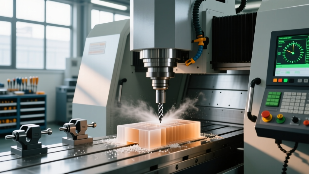
Standard multi-flute carbide end mills designed for steel or aluminum are largely ineffective for plastics. The primary failure mode is chip packing in the flutes, which rapidly increases cutting forces and shatters the tool or melts the part. Operators must be trained to select tools based on the specific polymer's durometer and glass transition temperature (Tg).
According to Harvey Tool's machining guidelines, unpolished or lightly honed flutes are often preferable for sticky plastics like UHMW and PTFE, as a mirror-polished flute can actually increase chip adhesion through vacuum effects. Conversely, cast acrylic requires a razor-sharp, polished O-flute to prevent micro-chipping and crazing.
| Material Class | Recommended Tool Geometry | Industry Standard Example | Helix Angle |
|---|---|---|---|
| Cast Acrylic (PMMA) | Single O-Flute, High Polish | Onsrud 63-700 Series | 40° - 45° |
| Polycarbonate (PC) | Single/Double Flute, Sharp Rake | Onsrud 63-800 Series | 35° |
| Delrin / Acetal (POM) | 2-Flute Carbide, High Relief | Harvey Tool 16000 Series | 30° |
| PTFE / UHMW-PE | Single Flute, Unpolished Gullet | Standard HSS or Carbide O-Flute | 25° - 30° |
| PEEK (Unfilled) | 3-Flute Carbide, AlTiN Coated | Sandvik Coromant Plastics Grade | 35° |
Workholding: Mitigating Elastic Memory and Creep
Plastics exhibit high elastic recovery and cold flow (creep) under sustained mechanical pressure. An operator trained in metal workholding will routinely over-torque clamps, inducing internal stresses that cause the part to warp the moment it is unclamped. Training must focus on distributed holding forces and torque limitation.
Mechanical Clamping Limits
- Acetal (Delrin): Limit clamping pressure to prevent permanent deformation. Use stepped jaws with a minimum 0.5-inch contact surface. Maximum torque on M8 step-clamp studs should not exceed 15 ft-lbs.
- Polycarbonate: Highly susceptible to stress cracking. Never use sharp-edged clamps directly on the material. Interpose 1/16-inch neoprene or urethane pads between the clamp and the workpiece to distribute the load.
- Two-Stage Clamping: For tight-tolerance bores, train operators to rough-machine the part, release the clamps to allow elastic recovery, and then re-clamp at 50% torque for the finishing pass.
Vacuum Table Operations
For sheet plastics (acrylic, PETG, HDPE), vacuum workholding is the industry standard. However, operators must understand CFM (Cubic Feet per Minute) requirements versus PSI. A porous sacrificial board (like MDF) requires high CFM, while a scored phenolic board requires less volume but higher vacuum pressure. Always route a 0.030-inch deep gasket groove around the part perimeter on the sacrificial layer and use 1/8-inch foam cord to seal the vacuum zone, preventing edge leaks that cause part shift during aggressive profiling.
Speeds, Feeds, and Thermal Management
Modern 2026 CNC spindles routinely exceed 24,000 RPM, which can be detrimental to plastics if feed rates are not scaled proportionally. The goal is to maximize the chipload (thickness of the chip) to act as a heat sink. If the chipload drops below 0.004 inches, the tool rubs, and the plastic melts.
'When machining PEEK, operators must respect the material's glass transition temperature of 143°C (289°F). Localized cutting temperatures that exceed this threshold will cause the polymer chains to relax, resulting in smeared surfaces and severe burr formation rather than clean shearing.' — Sandvik Coromant Machining Guidelines
Baseline Parameter Framework (1/2-inch Diameter Tool)
Cast Acrylic: 18,000 RPM | 120 IPM | 0.006" Chipload | Air Blast Cooling
Delrin (POM): 12,000 RPM | 150 IPM | 0.012" Chipload | Dry or Mist
UHMW-PE: 8,000 RPM | 90 IPM | 0.011" Chipload | Air Blast (Strictly Dry)
Nylon (Polyamide): 10,000 RPM | 100 IPM | 0.010" Chipload | Compressed Air Only
The Coolant Trap: Why Flood Cooling is Often Destructive
A critical training point for operators transitioning from metal to plastic is the danger of standard water-soluble flood coolants. Polyamides (Nylons) are highly hygroscopic. If machined with water-based coolants, Nylon can absorb up to 8% of its weight in moisture during a single shift. This causes catastrophic dimensional swelling, often rendering tight-tolerance aerospace or medical components scrap. For Nylon, PTFE, and UHMW, strictly use compressed air blasts or vortex cold-air guns to evacuate chips and manage heat.
For materials like Polycarbonate and Acetal that can tolerate liquid cooling, use a straight oil or a highly concentrated synthetic mist (MQL - Minimum Quantity Lubrication) rather than flood coolant. This provides boundary lubrication to prevent chip re-welding without inducing thermal shock or moisture absorption.
Troubleshooting Matrix: Operator Decision Tree
Post-training, operators should use this diagnostic matrix to identify and correct common CNC plastic machine errors on the shop floor without requiring engineering intervention.
Symptom: Gummy Chips Re-Welding to the Cutting Edge
Root Cause: Chipload is too thin, causing the tool to rub instead of shear. Alternatively, the tool gullet is too small for the volume of material being removed.
Corrective Action: Increase the feed rate by 20% or decrease RPM to achieve a minimum 0.008" chipload. Switch to a single O-flute tool to maximize gullet volume for chip evacuation.
Symptom: Part Dimensions Shrink/Warp After Unclamping
Root Cause: Mechanical clamps were over-torqued, inducing elastic memory and internal stress. The material returns to its unstressed state once released.
Corrective Action: Implement two-stage clamping. Rough the part, release clamps, re-torque to 50% for finishing. Alternatively, transition to vacuum workholding or use soft jaws with maximum surface contact.
Symptom: Micro-Crazing or Stress Cracks in Polycarbonate
Root Cause: Dull tooling generating excessive cutting pressure, or the use of an incompatible cutting fluid that chemically attacks the polymer chains.
Corrective Action: Replace the end mill. Verify that any MQL fluid used is explicitly rated as non-reactive with Polycarbonate. Ensure the tool is not deflecting into the part wall during climb milling passes.
Symptom: Fuzzy or Hairy Edges on Fiber-Reinforced Plastics (G10/Garolite)
Root Cause: Standard carbide tools are being abraded by the glass fibers, dulling the cutting edge within minutes and tearing the resin matrix.
Corrective Action: Switch immediately to Polycrystalline Diamond (PCD) tipped tooling or CVD diamond-coated end mills. Utilize high-speed spindles (20,000+ RPM) with very light radial engagement (stepover of 5-10% of tool diameter) to shear the fibers cleanly.
Advanced Chip Evacuation Techniques
When deep-pocket milling materials like PTFE or Delrin, chips tend to pack tightly at the bottom of the cavity, acting as an insulator and causing the tool to overheat. Operators must be trained to program peck-milling cycles or utilize through-spindle air blast (TSA) systems. If the CNC plastic machine lacks TSA, program a G-code macro that retracts the tool completely from the bore every 3 passes, allowing an external air nozzle to clear the cavity. Never rely on the operator to manually blow out chips while the spindle is at idle; automated evacuation cycles ensure consistency and prevent thermal buildup in high-volume production runs.
By enforcing these strict operational parameters, tooling selections, and diagnostic frameworks, machine shops can drastically reduce scrap rates and achieve the mirror finishes and tight tolerances demanded by modern medical, aerospace, and semiconductor plastic components.