Technical Specs: How a Desktop CNC Machine for Metal Cuts Steel
Analyze spindle torque, ball screw rigidity, and cutting parameters to understand how a desktop CNC machine for metal handles steel and aluminum.
The Physics of Micro-Milling: Rigidity vs. Cutting Forces
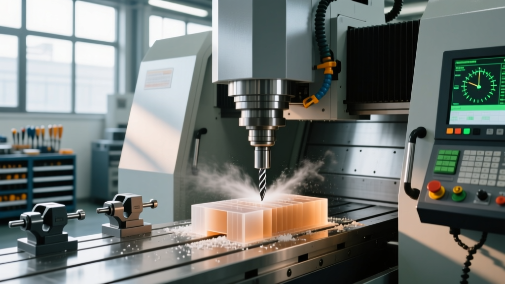
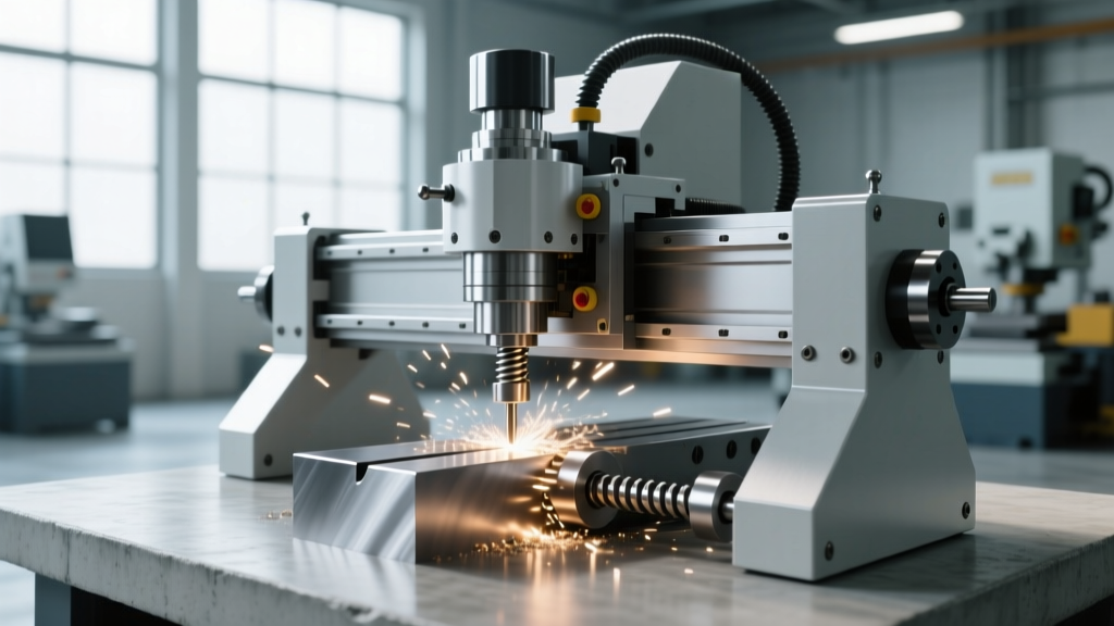
Cutting steel on a benchtop footprint requires overcoming severe physical limitations regarding mass, damping, and torque delivery. When evaluating a desktop CNC machine for metal, the primary limiting factor is rarely the spindle's top speed; it is the machine's static and dynamic rigidity. Unlike industrial VMCs (Vertical Machining Centers) that weigh several tons and utilize massive cast-iron columns to absorb harmonic vibrations, desktop mills must rely on optimized geometry and precision drive trains to prevent tool deflection and chatter.
⚠️ Critical Warning: Aluminum Extrusion FramesMany entry-level desktop CNCs utilize 80/20 aluminum extrusions for their structural frame. While sufficient for routing wood or engraving plastics, aluminum extrusions lack the damping coefficient required for milling steel. The resonant frequency of extruded aluminum frames often aligns with the harmonic chatter generated by carbide endmills cutting ferrous metals, leading to catastrophic tool failure and poor surface finishes. True metal-cutting benchtop mills require cast-iron or heavily ribbed steel weldments.
Spindle Architecture: Decoding the Torque Curve
The spindle is the heart of any CNC mill, but desktop machines face a distinct engineering challenge: delivering high torque at low RPMs without requiring a massive, heavy motor. Industrial mills use gear-driven or belt-driven heads to multiply torque, but desktop machines typically rely on direct-drive or single-stage belt configurations.
VFD-Driven AC vs. BLDC Spindles
For machining steel, the torque curve is vastly more important than maximum RPM. Steel requires high cutting forces at lower spindle speeds (typically 800 to 2,000 RPM for a 1/4-inch endmill), whereas aluminum thrives at high speeds (4,000 to 10,000+ RPM).
| Spindle Type | Torque Delivery | Best Application | Example Model |
|---|---|---|---|
| VFD + 3-Phase AC Motor | High torque at low RPM; maintains constant torque up to base speed. | Steel, Titanium, heavy DOC in Aluminum. | Tormach PCNC 440 (0.75 HP) |
| BLDC (Brushless DC) | Low torque at low RPM; torque peaks only at high RPM. | PCB milling, soft plastics, light aluminum. | Bantam Tools Desktop CNC |
| High-Speed Direct Drive | Extremely low torque; relies on ultra-high RPM and micro-tooling. | Micro-machining, 5-axis dental, jewelry. | Pocket NC V2-50 (120W) |
As of 2026, a fully equipped Tormach PCNC 440 package retails between $6,500 and $8,200 depending on the enclosure and tooling package. Its VFD-controlled spindle delivers peak torque around 2,200 RPM, making it highly capable of cutting 1018 cold-rolled steel. Conversely, the 5-axis Pocket NC V2-50 commands upwards of $18,000 for professional tiers, utilizing a 30,000 RPM spindle that requires specialized micro-tooling and harmonic strain-wave gearing to manage cutting forces in harder metals.
Drive Train Mechanics: Eliminating Backlash at the Micro-Level
Rigidity in the cutting head is useless if the drive train introduces backlash or flex under load. Desktop CNC machines designed for metal must utilize precision ground ball screws rather than standard lead screws or timing belts.
- C3 or C5 Grade Ball Screws: Industrial benchtop mills use C3 grade ball screws, which guarantee a lead accuracy of 0.0002 inches per foot. This ensures that when the controller commands a 0.005-inch step-over, the table actually moves exactly 0.005 inches, preventing tool rubbing and premature wear.
- Preloaded Double-Nut Configurations: To eliminate axial backlash, high-end desktop mills use a double-nut setup with a precision spacer or spring preload. This forces the ball bearings against both sides of the screw thread simultaneously, reducing backlash to less than 0.0001 inches.
- Linear Guideways vs. Dovetails: While traditional dovetail ways offer excellent damping for heavy interrupted cuts, modern desktop mills often use preloaded linear guideways (like Hiwin HG series) for lower friction and higher rapid traverse rates, provided the carriage blocks are oversized to resist moment loads.
Material-Specific Cutting Parameters for Benchtop Mills
Programming feeds and speeds for a desktop CNC machine for metal requires a fundamental shift in strategy. You cannot simply scale down industrial parameters. The machine's lower mass dictates strict limits on the Axial Depth of Cut (ADOC) and Radial Depth of Cut (RDOC) to prevent stalling the spindle or inducing chatter.
| Material | Tooling (1/4" Carbide) | Spindle RPM | Feed Rate (IPM) | Max ADOC / RDOC |
|---|---|---|---|---|
| 6061-T6 Aluminum | 2-Flute ZrN Coated | 4,500 | 27 IPM | 0.100" / 0.025" |
| 1018 Cold Rolled Steel | 3-Flute AlTiN Coated | 1,400 | 8.5 IPM | 0.040" / 0.015" |
| Ti-6Al-4V (Titanium) | 4-Flute Variable Helix | 800 | 3.2 IPM | 0.020" / 0.010" |
Note: These parameters assume a rigid benchtop mill with a 0.5 to 0.75 HP spindle. If your machine utilizes a router-style spindle, reduce ADOC by 50% and increase RPM to maintain surface footage.
Toolholder Runout and ER Collet Limitations
On a desktop form factor, toolholder runout is magnified. A standard ER16 collet system, common on benchtop mills, can exhibit 0.0002 to 0.0004 inches of runout at the nut. While acceptable for roughing, this runout causes uneven chip loading on the flutes of a Harvey Tool miniature end mill, drastically reducing tool life when machining abrasive materials like stainless steel or titanium.
"When machining steel on a desktop CNC, always utilize a torque wrench to tighten the ER collet nut to the manufacturer's exact specification. Under-tightening causes the tool to pull out under heavy axial loads, while over-tightening distorts the collet geometry and exacerbates runout."
For high-precision finishing passes, operators should upgrade to ER16-UA (Ultra Accuracy) collets or invest in a dedicated endmill holder system that guarantees less than 0.0001 inches of TIR (Total Indicated Runout) at 3x diameter projection.
Troubleshooting Harmonic Chatter on Desktop Form Factors
Chatter is the acoustic manifestation of the tool and workpiece vibrating out of phase. Because desktop CNCs lack the mass to absorb these vibrations passively, operators must actively tune the cutting dynamics. Follow this step-by-step decision tree to eliminate chatter:
- Verify Tool Stick-Out: Reduce the tool stick-out to the absolute minimum required for the Z-depth. Every 0.100-inch reduction in stick-out increases tool rigidity exponentially (deflection is proportional to the cube of the length).
- Switch to Climb Milling: Ensure your toolpaths are utilizing climb milling (down milling). Conventional milling pushes the workpiece away from the cutter, exacerbating backlash in the ball screws and inducing chatter.
- Implement Variable Helix Tooling: Standard endmills have uniform flute spacing, which creates a consistent harmonic frequency. Variable helix and variable pitch endmills break up this frequency, effectively canceling out the resonant vibration before it amplifies.
- Tune the Spindle Speed: If chatter persists, alter the spindle RPM by exactly 10% to 15%. This shifts the tooth-engagement frequency out of the machine's natural harmonic sweet spot, often resulting in an immediate cessation of chatter and a mirror-like surface finish.
When slotting or profiling steel on a desktop CNC, avoid full-width engagement. Utilize Adaptive Clearing or Trochoidal milling toolpaths (available in Fusion 360 and Mastercam). These toolpaths maintain a constant, low radial engagement (typically 5% to 10% of the tool diameter) while utilizing high feed rates, keeping cutting forces well within the torque limits of a benchtop spindle.