Spindle Feed Rate Optimization vs EDM CNC Machine Parameters
Compare CNC spindle speed and feed rate optimization with EDM CNC machine servo parameters to maximize material removal rates and surface finish.
The Physics of Material Removal: Rotary Shear vs. Thermal Erosion
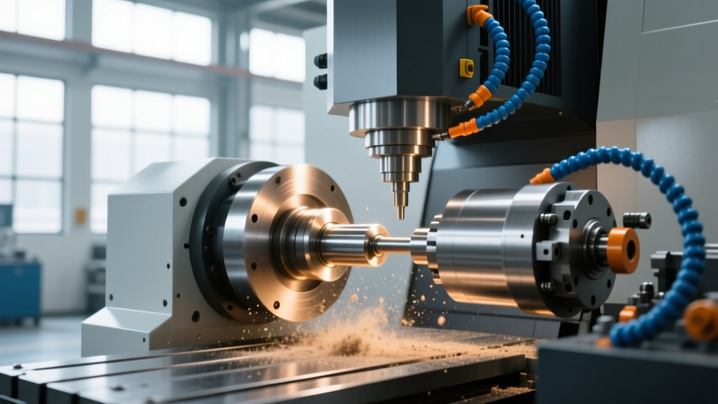
Optimizing material removal rates (MRR) requires a fundamental understanding of how energy is transferred to the workpiece. In traditional subtractive manufacturing, CNC spindle speed and feed rate optimization relies on mechanical shear force. The rotating spindle generates the cutting speed ($V_c$), while the feed rate ($V_f$) advances the tool through the material, creating a specific chip load. Conversely, an EDM CNC machine (Electrical Discharge Machining) eliminates mechanical cutting forces entirely, replacing spindle dynamics with thermal erosion via controlled electrical sparks. While the physical mechanisms differ radically, the ultimate optimization goal remains identical: maximizing MRR while maintaining strict surface finish (Ra) tolerances and preventing catastrophic tool failure.
Core Parameter Distinction:Milling/Turning: Optimizes Spindle RPM, Feed per Tooth ($f_z$), and Depth of Cut ($a_p$).
EDM CNC Machine: Optimizes Wire Feed Rate, Servo Gap Voltage, Pulse On-Time ($T_{on}$), and Pulse Off-Time ($T_{off}$).
Traditional CNC Spindle Speed and Feed Rate Optimization
Achieving peak efficiency in mechanical CNC milling requires balancing the spindle speed against the feed rate to avoid two primary failure modes: chatter (which destroys surface finish and tool life) and chip packing (which causes tool breakage). According to Sandvik Coromant's machining guidelines, the foundational formula for table feed rate is $V_f = f_z \times z \times n$, where $f_z$ is feed per tooth, $z$ is the number of flutes, and $n$ is spindle speed.
Calculating the Sweet Spot: A 304 Stainless Steel Case Study
Consider machining 304 stainless steel with a 12.7mm (1/2-inch) diameter, 4-flute solid carbide endmill. The recommended cutting speed ($V_c$) is approximately 150 m/min. Using the formula $n = \frac{V_c \times 1000}{\pi \times D_c}$, the target spindle speed is 3,770 RPM. If the recommended chip load ($f_z$) is 0.05 mm/tooth, the optimized feed rate becomes 754 mm/min.
| Material | Tool Diameter | Spindle Speed (RPM) | Feed Rate (mm/min) | Optimization Focus |
|---|---|---|---|---|
| 304 Stainless | 12.7mm (4-Flute) | 3,770 | 754 | Avoid work hardening |
| 6061 Aluminum | 12.7mm (3-Flute) | 12,000 | 2,880 | Chip evacuation |
| Ti-6Al-4V | 12.7mm (5-Flute) | 1,100 | 165 | Thermal management |
Advanced optimization requires accounting for the chip thinning effect. When the radial depth of cut ($a_e$) is less than half the tool diameter, the actual chip thickness decreases. Operators must increase the feed per tooth to maintain the recommended chip load, utilizing machining calculators to prevent the tool from rubbing rather than cutting, which generates excessive heat and accelerates flank wear.
How an EDM CNC Machine Replaces Spindle Dynamics
Because an EDM CNC machine does not use a rotating cutting tool, the concepts of spindle RPM and mechanical feed per tooth are entirely irrelevant. Instead, MRR is governed by the electrical parameters and the speed at which the machine's servo axes maintain the spark gap. Modern platforms, such as the GF Machining Solutions CUT E series, utilize advanced adaptive control systems to optimize these non-mechanical feed rates in real-time.
Wire Feed Rate and Tension in Wire EDM
In Wire EDM, the 'feed rate' is split into two distinct vectors: the X/Y axis contouring speed and the physical wire feed rate. The wire (typically 0.25mm brass or coated wire) is fed through the workpiece at speeds ranging from 300 mm/min to over 1,500 mm/min. Optimizing this requires balancing the wire feed speed against the flushing pressure. If the contouring speed outpaces the wire feed rate, the wire wears down, causing taper errors and eventual breakage. Conversely, excessive wire feed wastes expensive consumables without increasing MRR.
Z-Axis Servo Optimization in Sinker EDM
Sinker EDM relies on a Z-axis servo motor to feed the electrode into the workpiece. The optimization metric here is gap voltage tracking. The CNC controller monitors the voltage across the spark gap (typically 40V to 120V). If the gap becomes contaminated with debris, the voltage drops, and the servo feed rate must instantly retract (jump flush) to clear the dielectric fluid. Tuning the servo gain and jump cycle parameters is the Sinker EDM equivalent of optimizing chip evacuation in mechanical milling.
Parameter Matrix: Mechanical Milling vs. EDM CNC Machine
Understanding the direct translation of optimization goals between mechanical and thermal processes allows manufacturing engineers to select the right process for complex geometries.
| Optimization Goal | Mechanical CNC Milling | EDM CNC Machine |
|---|---|---|
| Maximize MRR | Increase $a_p$ and $f_z$ to machine limits | Increase Peak Current ($I_p$) and Pulse On-Time ($T_{on}$) |
| Improve Surface Finish | Reduce $f_z$, increase Spindle RPM, use wiper inserts | Reduce $I_p$, decrease $T_{on}$, increase $T_{off}$, reduce wire feed |
| Prevent Tool Failure | Avoid chatter via Stability Lobe Diagrams | Prevent arcing via adaptive gap voltage servo control |
| Manage Heat | Flood coolant or MQL, high-speed spindle air blast | Submerge in dielectric fluid, optimize flushing pressure |
Real-World Edge Cases and Failure Modes
Theoretical calculations rarely survive contact with the shop floor. Recognizing the specific failure modes of both technologies is critical for troubleshooting.
- Mechanical Chatter vs. EDM Arcing: In milling, chatter occurs when the spindle speed excites the natural harmonic frequency of the tool-holder-workpiece system, leaving visible regenerative marks on the surface. In an EDM CNC machine, the equivalent failure is 'arcing'—when the spark gap collapses and continuous DC current flows, melting the electrode and pitting the workpiece. While chatter is solved by altering RPM by 5-10%, arcing is solved by increasing the Pulse Off-Time ($T_{off}$) to allow the dielectric fluid to de-ionize.
- The Corner Radius Trap: When milling a tight internal corner, the tool engagement angle spikes to 180 degrees, causing sudden shock loads and tool deflection. Programmers must use trochoidal milling to maintain constant tool engagement. In Wire EDM, cutting a tight internal corner causes the wire to dwell, overcutting the corner due to the spark gap lag. EDM operators must program 'corner burn' offsets or reduce the contouring feed rate by 30-50% specifically in the corner blocks of the G-code.
- Hardened Steels (>50 HRC): Mechanical spindle optimization becomes nearly impossible in heavily hardened tool steels due to extreme cutting forces and rapid carbide degradation. This is the exact threshold where transitioning to an EDM CNC machine becomes mandatory, as electrical discharge erosion is entirely unaffected by workpiece hardness.
Actionable Calibration Checklist for Operators
Before initiating a production run, verify the following parameters based on your machine type:
- For Mechanical CNC: Verify the actual tool diameter using a presetter. A 0.02mm deviation in a 10mm endmill alters the true spindle RPM requirement by nearly 1%. Confirm that the CAM software's chip thinning compensation is active for radial depths of cut below 50%.
- For Wire EDM: Check the wire tension meter. A 0.25mm wire should typically be tensioned between 1.2 kg and 1.5 kg. Inspect the lower diamond guide for wear; a worn guide allows wire vibration, destroying the surface finish regardless of how well the pulse parameters are tuned.
- For Sinker EDM: Calibrate the Z-axis jump cycle. For deep cavities with poor flushing, set the jump height to at least 2x the depth of the cavity to ensure complete dielectric exchange, even if it slightly reduces the net Z-axis feed rate.