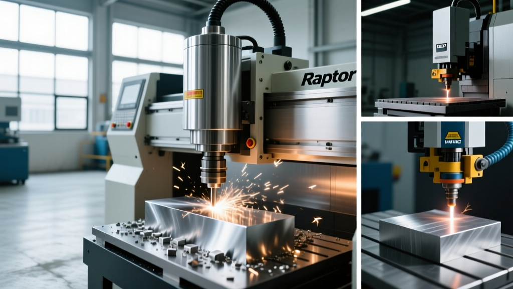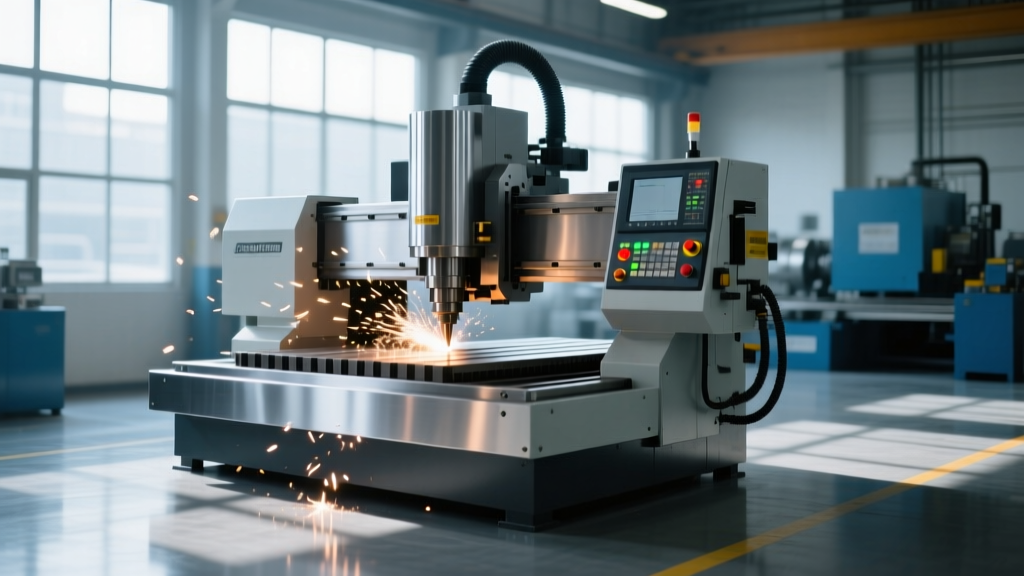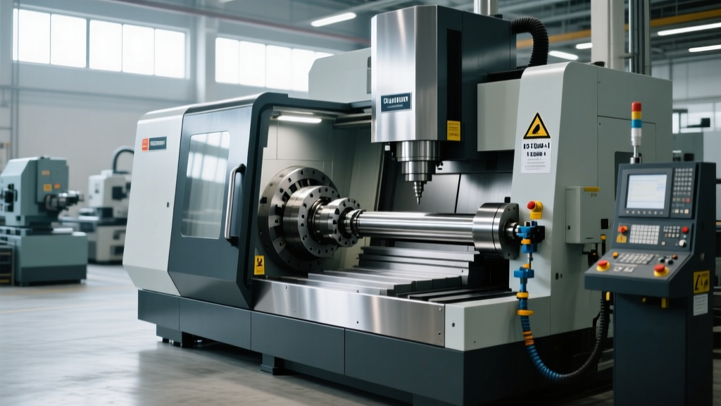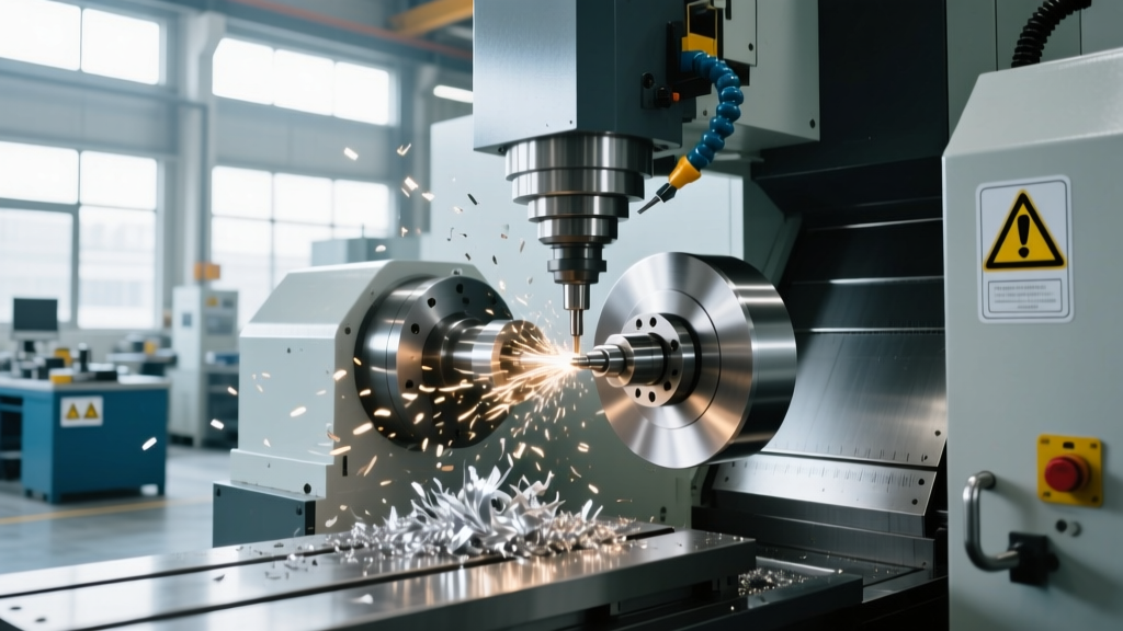
Spindle Speed & Feed Rates for CNC Machine Operation Stations
Master spindle speed and feed rate optimization at CNC machine operation stations. Learn material baselines, chip thinning, and HMI load tuning.
The Physics of the Cut: SFM, RPM, and IPT
Calculating theoretical speeds and feeds is only the first step in the machining process. True optimization occurs when the operator translates those calculations into physical reality at the CNC machine operation stations, adjusting for machine rigidity, tool runout, and real-time harmonic feedback. The core kinematics of milling rely on two primary metrics: Surface Feet per Minute (SFM or Vc) and Inches per Tooth (IPT or fz).
SFM dictates the speed at which the cutting edge engages the workpiece material. It is a material-dependent constant that determines the heat generated at the shear zone. IPT dictates the thickness of the chip being evacuated. If IPT is too low, the tool rubs rather than cuts, leading to work hardening and premature edge degradation. If IPT is too high, the cutting forces exceed the tool's transverse rupture strength, causing catastrophic edge chipping.
Core Shop Floor Formulas
Spindle Speed (RPM): RPM = (3.82 × SFM) / Tool Diameter
Feed Rate (IPM): IPM = RPM × IPT × Number of Flutes
Note: The constant 3.82 is derived from 12 / π, converting inches to feet and linear speed to rotational speed.
Radial Chip Thinning: The Hidden Feed Rate Multiplier
One of the most common errors made by programmers and operators at the CNC machine operation stations is failing to compensate for Radial Chip Thinning (RCT). When executing high-efficiency milling (HEM) or adaptive clearing toolpaths, the Radial Depth of Cut (RDOC) is often limited to 5%–15% of the tool diameter.
Because the tool enters the material at a shallow arc, the actual chip thickness is significantly thinner than the programmed IPT. If the feed rate is not increased to compensate for this geometry, the cutting edge will rub against the workpiece, generating excessive heat and destroying the tool coating in minutes.
- RDOC at 50% of Tool Diameter: Chip thickness is roughly 86% of programmed IPT. Multiply feed by 1.15x.
- RDOC at 20% of Tool Diameter: Chip thickness is roughly 60% of programmed IPT. Multiply feed by 1.66x.
- RDOC at 5% of Tool Diameter: Chip thickness is roughly 31% of programmed IPT. Multiply feed by 3.2x.
According to the Harvey Tool Speeds and Feeds Guide, modern CAM software automatically calculates these adjusted feed rates. However, when an operator manually overrides the feed rate dial at the control panel, they risk dropping the actual chip load below the minimum threshold required for effective heat evacuation.
Material-Specific Baselines for Modern Tooling
Tooling coatings have evolved significantly. Advanced nano-composite coatings like nACRo (Aluminum Chromium Nitride) and ZrN (Zirconium Nitride) allow for much higher SFM values than traditional TiAlN. Below is a baseline matrix for 3-flute and 4-flute solid carbide endmills utilizing modern coatings.
| Workpiece Material | Target SFM (Vc) | Base IPT (fz) | Recommended Tool Geometry |
|---|---|---|---|
| 6061-T6 Aluminum | 1,800 - 2,500 | 0.006" - 0.010" | 3-Flute, ZrN, 40° Helix, Polished Flutes |
| 304 Stainless Steel | 250 - 350 | 0.002" - 0.004" | 4-Flute, AlTiN, Variable Pitch |
| Ti-6Al-4V Titanium | 120 - 180 | 0.001" - 0.0025" | 5-Flute, nACRo, Eccentric Relief |
| Inconel 718 | 80 - 120 | 0.0008" - 0.0015" | 6-Flute, Ceramic or SiAlON Insert |
Navigating the CNC Machine Operation Station Interface
The interface where the human meets the machine—the CNC machine operation stations—provides critical real-time data that must be used to tune the theoretical parameters. Modern HMIs (Human-Machine Interfaces) like the Fanuc 0i-F Plus, Haas Next Generation Control (NGC), and Siemens Sinumerik Operate feature integrated spindle load meters and adaptive control algorithms.
Reading the Spindle Load Meter
The spindle load meter displays the percentage of available spindle motor torque being utilized.
- Roughing Operations: The load meter should ideally hover between 45% and 75%. If the load consistently sits below 20%, the tool is underutilized, and the feed rate should be increased to maximize material removal rate (MRR).
- Finishing Operations: Loads should remain under 30% to prevent tool deflection, which compromises dimensional accuracy and surface finish.
- Spiking Loads: If the meter frequently spikes to 100% or triggers the machine's overload alarm, the radial engagement is too high, or the chips are not evacuating the flute valleys effectively.
The Override Dial Strategy
Physical feed and speed override dials on the CNC machine operation stations are powerful diagnostic tools. When proving out a new program, operators should utilize the Single Block mode combined with the Feed Hold button, keeping the rapid override at 5% and feed override at 50%. Once the first cut is established and the sound of the shear zone is verified, the feed override can be incremented in 10% steps while monitoring the spindle load meter.
⚠️ WARNING: Peck Drilling OverridesNever reduce the feed rate override below 100% during a G83 (Peck Drilling) or G73 (High-Speed Peck) cycle at the operation station unless the machine specifically supports synchronous spindle-feed override scaling. Reducing the feed rate without proportionally reducing the spindle RPM alters the programmed chip load, often resulting in stringy chips that pack inside the flutes and snap the drill upon retraction.
Diagnosing Cut Anomalies via Audio and Visual Feedback
While the Sandvik Coromant Milling Knowledge Base provides extensive data on tool wear patterns, the operator at the CNC machine operation stations must diagnose issues in real-time using audio cues and visual inspection of the chip stream.
- High-Pitch Squeal (Harmonic Chatter): This indicates tool deflection and regenerative chatter. The cutting edge is vibrating against the workpiece. Fix: Reduce the spindle speed (RPM) by 10-15% to shift the harmonic frequency, or increase the feed rate to force the tool against the workpiece wall, dampening the vibration.
- Low-Pitch Rumble: This is typically workpiece vibration or fixture inadequacy, not tool chatter. The part is moving in the vise. Fix: Reduce the axial depth of cut (ADOC) or add secondary fixturing/clamping. Adjusting speeds and feeds at the control panel will not solve a rigidity issue.
- Blue/Purple Chips in Steel: Indicates that heat is not being carried away by the chip. The SFM is too low, or the tool is rubbing. Fix: Increase the SFM (RPM) or verify that the flood coolant is penetrating the shear zone, not just deflecting off the chip stream.
Adaptive Control and Closed-Loop Feedback
Modern CNC machine operation stations are increasingly equipped with closed-loop adaptive control systems. Features like Haas Adaptive Control (HAC) or Siemens Adaptation Control monitor the spindle load in milliseconds and automatically adjust the feed rate to maintain a constant, user-defined load target.
When utilizing these systems, the operator's role shifts from manual dial-turning to parameter configuration. The operator must input the correct Target Load (e.g., 65%) and the Maximum Feed Override Limit (e.g., 150%) into the HMI. This allows the machine to safely accelerate through air cuts and low-engagement corners while automatically backing off the feed rate when the tool encounters a full-width slot or a hard spot in the casting.
"The most dangerous habit at the CNC machine operation stations is leaving the feed override dial at a permanent 100% while running adaptive trochoidal toolpaths. The CAM software has already calculated the exact feed rate required to maintain chip thinning compensation. Manual overriding at the station breaks the mathematical relationship between the RDOC and the chip load, guaranteeing premature tool failure."
Synthesizing Theory and Station Execution
Optimizing spindle speeds and feed rates is not a static programming exercise; it is a dynamic physical process. By understanding the mathematics of radial chip thinning, leveraging the real-time telemetry available on modern HMIs, and correctly interpreting audio-visual feedback from the cutting zone, operators can push CNC machinery to its absolute mechanical limits while maintaining tool life and part quality.