Feed Rate & Spindle Speed for CNC Machine Automotive Parts
Master spindle speed and feed rate optimization for CNC machine automotive parts. Learn exact RPM calculations, chip load formulas, and material specs.
The Physics of Chip Formation in Automotive Machining
Optimizing spindle speed and feed rate for CNC machine automotive parts requires moving beyond generic catalog recommendations. Automotive manufacturing demands extreme consistency, where a deviation of 0.002 inches in tool deflection can scrap a $400 transmission housing or compromise the sealing surface of an engine block. The fundamental goal is to maintain the correct chip thickness to carry heat away from the cutting zone while maximizing the Material Removal Rate (MRR).
In high-volume automotive production, cycle time reductions of just 2 seconds per part translate to millions of dollars in saved overhead annually. Achieving this requires a precise synthesis of spindle RPM, feed per tooth (FPT), and depth of cut, tailored to the specific metallurgical properties of the workpiece.
Core Optimization Formulas
1. Spindle Speed (RPM):
RPM = (SFM × 3.82) / Tool Diameter (inches)
Where SFM is Surface Feet per Minute, dictated by the workpiece material and tool coating.
2. Feed Rate (IPM):
IPM = RPM × Feed Per Tooth (FPT) × Number of Flutes
FPT must exceed the material's elastic recovery threshold to prevent rubbing, which destroys tool life.
3. Metal Removal Rate (MRR):
MRR (in³/min) = Radial Depth of Cut × Axial Depth of Cut × IPM
Reference: Sandvik Coromant's official milling formulas and definitions.
Material-Specific Baselines: Automotive Alloys
Automotive components utilize a narrow but demanding range of materials. The parameters below assume a rigid machining center (e.g., Makino a61nx or Heller H2000) with a high-pressure through-spindle coolant (TSC) system operating at a minimum of 70 bar (1000 PSI).
| Automotive Material | Typical Application | Tooling Requirement | Target SFM | FPT (inches) |
|---|---|---|---|---|
| A356-T6 Cast Aluminum (7-11% Si) | Engine blocks, cylinder heads | PCD (Polycrystalline Diamond) or TiB2 coated carbide | 3,000 - 5,000 | 0.008 - 0.015 |
| 6061-T6 Extruded Aluminum | EV battery enclosures, suspension uprights | Uncoated polished carbide, ZrN coated | 1,800 - 2,500 | 0.006 - 0.010 |
| 4140 Pre-Hardened Steel (28-32 HRC) | Drive shafts, steering racks, gears | AlTiN or AlCrN coated micro-grain carbide | 350 - 450 | 0.004 - 0.007 |
| Ductile Iron (60-40-18) | Differential housings, brake calipers | CVD coated thick-edge carbide | 400 - 550 | 0.005 - 0.008 |
Spindle Speed Dynamics: HSK vs. CAT Tapers in High-RPM Auto Production
When optimizing spindle speed for CNC machine automotive parts, the toolholder interface is just as critical as the RPM number itself. For aluminum components like EV battery trays, machining centers utilize high-frequency spindles capable of 20,000 to 24,000 RPM. At these speeds, centrifugal force causes the spindle nose to expand radially.
The HSK-A63 Advantage for Aluminum
Traditional CAT40 or BT40 toolholders rely on a 7:24 taper with a pull-stud retention system. Above 12,000 RPM, the spindle nose expands, causing the taper to pull deeper into the spindle. This alters the Z-axis tool length offset dynamically, leading to depth errors in critical automotive sealing surfaces. HSK (Hollow Shank Taper) toolholders utilize a 1:10 taper with a simultaneous face-and-taper clamping mechanism. As centrifugal force increases, the HSK holder expands outward, actually tightening the face contact. For high-speed automotive milling, HSK-A63 or HSK-E50 is mandatory to maintain Z-axis repeatability within ±0.0002 inches.
⚠️ WARNING: Built-Up Edge (BUE) in Sticky Alloys
When machining 6061-T6 aluminum for suspension components, dropping below the critical SFM threshold (under 1,200 SFM) or utilizing a feed per tooth below 0.004 inches will cause the aluminum to weld to the cutting edge. This Built-Up Edge (BUE) alters the tool geometry, increases cutting forces, and ultimately leads to catastrophic tool failure and scrapped parts. Always prioritize a higher feed rate over a slower speed when dealing with gummy automotive aluminum alloys.
Feed Rate Optimization for EV Battery Enclosures
The shift toward electric vehicles has introduced massive, thin-walled 6061-T6 aluminum battery enclosures to the automotive machining floor. These parts feature deep pockets, thin floor sections (often 2.0mm to 3.0mm), and strict flatness tolerances to ensure proper thermal pad compression.
Trochoidal Milling for Slotting and Bossing
Conventional slotting with a 1/2-inch end mill at full radial engagement (RDOC = 100%) generates immense radial pressure, pushing thin walls out of tolerance and inducing chatter. To optimize feed rates without destroying the part, programmers must adopt trochoidal milling (also known as Adaptive Clearing or Volumill).
- Radial Depth of Cut (RDOC): Restricted to 5% - 8% of the tool diameter (e.g., 0.030" on a 1/2" tool).
- Axial Depth of Cut (ADOC): Increased to 1.5x or 2.0x the tool diameter to maintain MRR.
- Feed Rate Impact: Because the radial engagement is so low, the chip thins significantly. To maintain the required effective chip thickness, the programmed feed rate (IPM) can be increased by 300% to 500% compared to conventional milling.
According to Haas Automation's technical guidelines on high-speed machining, utilizing light radial cuts with high feed rates keeps the cutting forces directed axially down into the spindle, rather than radially into the thin walls of the battery tray.
Edge Case: Machining A356-T6 Engine Blocks with PCD
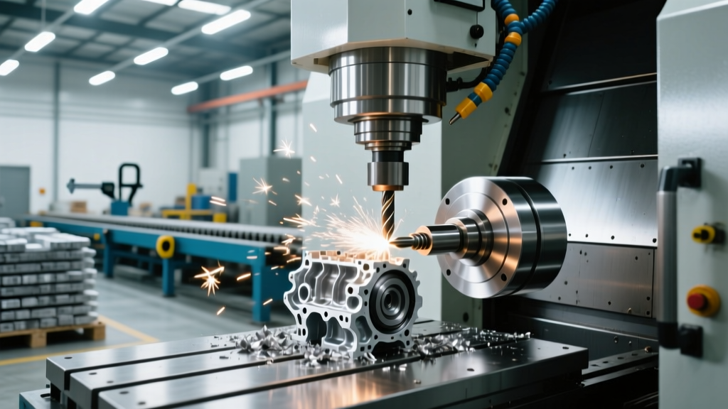
A356-T6 cast aluminum contains high levels of silicon (up to 11%), which acts like sandpaper on standard carbide tooling. A standard AlTiN coated carbide end mill might machine 40 engine blocks before flank wear exceeds 0.008 inches. In contrast, a Polycrystalline Diamond (PCD) tipped tool can machine 50,000+ blocks.
However, PCD tooling requires entirely different feed and speed parameters. PCD is exceptionally hard but brittle. It cannot withstand interrupted cuts at low speeds. When face-milling the deck surface of an engine block with a 4-inch PCD face mill:
- Spindle Speed: Set to 4,500 RPM (approx. 4,700 SFM).
- Feed Rate: 0.012 inches per tooth. With 8 effective cutting edges, this yields a feed rate of 450 IPM.
- Coolant Strategy: Air blast or MQL (Minimum Quantity Lubrication) is preferred over flood coolant. Flood coolant at these extreme speeds causes thermal shock to the PCD tips, leading to micro-chipping along the cutting edge.
Diagnostic Matrix: Adjusting Feeds and Speeds on the Fly
Even with perfect CAM programming, real-world variables like material hardness batch variations, tool wear, and machine rigidity require on-the-fly adjustments. Use this diagnostic matrix when troubleshooting automotive part machining anomalies.
| Symptom / Anomaly | Root Cause Analysis | Corrective Action (Feed/Speed) |
|---|---|---|
| High-Pitch Squeal (Chatter) during peripheral milling of suspension knuckles. | Harmonic resonance between tool overhang and spindle frequency. Radial cutting forces are too high. | Decrease RPM by 10-15% to shift the harmonic frequency. Reduce RDOC by 20%. Do not decrease feed rate, as this increases rubbing. |
| Poor Surface Finish (visible feed marks) on 4140 steel steering shafts. | Tool deflection under heavy radial load, or insert nose radius is too small for the programmed feed. | Decrease FPT by 30% and increase RPM by 15%. Alternatively, switch to an insert with a larger wiper facet or nose radius (e.g., from 0.8mm to 1.2mm). |
| Rapid Flank Wear on carbide drills in cast iron differential housings. | Cutting zone temperature exceeding the thermal limit of the AlTiN coating. Chips are not evacuating, causing secondary re-cutting. | Increase TSC coolant pressure to 100+ bar. Increase feed rate (IPR) by 10% to generate a thicker chip that carries more heat away from the cutting edge. |
| Burred Edges / Exit Burrs when drilling through-holes in aluminum transmission valve bodies. | The drill is pushing the material out rather than shearing it cleanly at the breakthrough point. Feed rate is too high at exit. | Program a "breakthrough feed reduction." Drop the Z-axis feed rate by 50% for the final 0.050" of travel, then retract at rapid traverse. |
Summary: The Shift Toward Data-Driven Machining
Optimizing CNC machine automotive parts is no longer about relying on machinist intuition alone. Modern automotive tier-1 suppliers utilize spindle load monitoring and acoustic emission sensors to dynamically adjust feed rates in real-time. By understanding the fundamental physics of chip formation, selecting the correct toolholder interface for high-RPM spindles, and applying material-specific baseline formulas, manufacturers can drastically reduce cycle times while maintaining the micron-level tolerances required by modern automotive powertrains and EV platforms.