Understanding CNC Machine Sex: Controller Interface Connectors
Master CNC machine sex and controller interface connectors. Learn best practices for mating DB25, M12, and RJ45 cables to prevent pin damage and downtime.
The Physical Layer: Defining CNC Machine Sex in Controller Interfaces
In industrial electrical engineering and shop-floor parlance, the term CNC machine sex refers to the physical gender of mating connectors—specifically, the male (exposed pins or plugs) and female (recessed sockets or receptacles) configurations that link the machine controller to external networks, pendants, and I/O modules. While modern manufacturing focuses heavily on software protocols like MTConnect and OPC UA, the physical layer remains the most common point of failure. A misunderstood connector gender, a forced mating attempt, or a mismatched null-modem adapter can instantly halt a multi-axis machining center.
As of 2026, with the widespread adoption of the Siemens SINUMERIK ONE and Haas Next Generation Control (NGC) systems, operators must navigate a hybrid landscape. Machines feature both legacy serial ports for older peripherals and high-speed industrial Ethernet ports for smart factory integration. Understanding the exact mating requirements, pinouts, and locking mechanisms of these interfaces is a critical operator competency that prevents costly hardware damage and communication alarms.
⚠️ CRITICAL WARNING: Never force a male pin array into a female socket. Bent pins on a Fanuc 31i-B5 controller mainboard I/O port often require a complete board replacement, costing upwards of $4,500 and resulting in 48+ hours of machine downtime.Standard CNC Controller Interface Connectors (2026 Specifications)
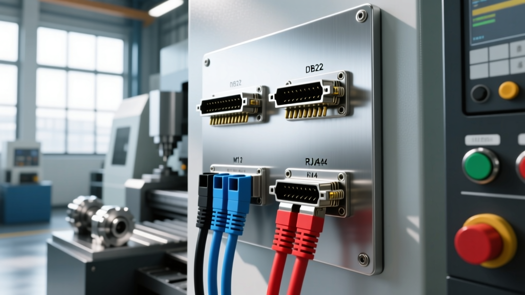
Operators must be able to visually identify connector types and their corresponding genders before attempting to interface any peripheral, DNC (Distributed Numerical Control) drip-feed system, or IoT gateway. The table below outlines the standard physical interfaces found on modern and legacy CNC controllers.
| Connector Type | Machine Port Sex | Cable End Sex | Primary Application | Controller Examples |
|---|---|---|---|---|
| DB9 / DB25 | Male (Pins) | Female (Sockets) | Legacy RS-232 Serial DNC | Fanuc 0i-F, Mazak Mazatrol Smooth |
| RJ45 (Ethernet) | Female (Receptacle) | Male (Plug) | Network / MTConnect / OPC UA | Haas NGC, Siemens SINUMERIK ONE |
| M12 D-Coded | Female (Receptacle) | Male (Plug) | Industrial Ethernet (IP67) | Heidenhain TNC7, Okuma OSP-P500 |
| USB Type-A | Female (Receptacle) | Male (Plug) | Local Program Transfer / Backup | Universal across modern controls |
Legacy Serial vs. Modern Ethernet: Navigating the Transition
Many job shops in 2026 still rely on RS-232 serial connections for older 3-axis mills and lathes. The physical interface for RS-232 is notoriously fragile. The male pins on a DB9 or DB25 controller port protrude and are highly susceptible to bending if the female cable connector is inserted at an angle.
Furthermore, serial communication requires precise crossover wiring. A standard straight-through cable will not work; operators must use a 'null modem' cable, which internally crosses the Transmit (TX) and Receive (RX) pins. Attempting to fix a communication error by simply swapping male/female gender changers (adapters) without verifying the internal pinout crossover is a leading cause of serial port timeouts.
💡 Operator Tip: When upgrading a legacy machine to an IoT network, avoid using cheap plastic gender changers and null-modem adapters stacked together. Instead, purchase a pre-molded, shielded RS-232 Null Modem cable with integrated thumb-screws to ensure a rigid, single-piece physical connection.Conversely, modern controllers utilize RJ45 and M12 connectors for Ethernet/IP and PROFINET. RJ45 ports (female on the controller) feature a delicate plastic locking tab on the male cable plug. In high-vibration CNC environments, this tab frequently snaps, leading to intermittent data drops during active DNC drip-feeding, which can ruin a multi-hour aerospace roughing cycle. For these environments, the industry has standardized on M12 D-coded circular connectors, which utilize a threaded knurled nut for a vibration-proof, IP67-rated seal.
Step-by-Step: Best Practices for Mating Controller Cables
Proper mating procedures extend the lifespan of the controller's I/O board and ensure uninterrupted data transfer. Follow this protocol when interfacing any peripheral to the CNC control:
- Visual Inspection of the 'Sex' and Pin Array: Before inserting any cable, use a flashlight to inspect the male pins on the controller port. Look for oxidized contacts, pushed-back pins, or bent alignment guides. For M12 connectors, ensure the internal keyway (the plastic notch that dictates alignment) is intact.
- Align and Seat Without Force: Align the female connector with the male port. For DB9/DB25 connectors, the D-shaped metal shield acts as a keying mechanism. If it does not slide in with zero resistance, stop immediately. You are likely misaligned or attempting to mate a 25-pin plug into a 9-pin adapter.
- Engage Locking Mechanisms to Spec:
- Thumb Screws (DB9/DB25): Tighten both sides evenly. Do not use pliers, as over-torquing can strip the internal standoff threads on the controller casing.
- M12 Circular Connectors: Hand-tighten the knurled nut until snug. For strict adherence to Society of Manufacturing Engineers (SME) industrial networking guidelines, apply exactly 0.5 Nm of torque using a calibrated torque screwdriver to ensure the IP67 seal is compressed without cracking the housing.
- RJ45 Ethernet: Ensure the locking tab clicks audibly. In high-vibration zones, apply a specialized RJ45 locking clip (e.g., Panduit RJ45 lock) to prevent accidental unplugging by passing personnel.
- Implement Strain Relief: Never let the weight of a heavy shielded cable hang directly from the controller port. Use zip-ties or magnetic cable mounts to secure the cable to the machine enclosure within 6 inches of the connector, transferring the mechanical load away from the solder joints on the controller PCB.
Troubleshooting Interface Communication Failures
When physical layer issues occur, the controller will throw specific alarms. Operators must know how to trace these alarms back to the connector mating.
Symptom: 'ALARM 114: SERIAL PORT TIMEOUT' (Haas NGC)
- Root Cause: The controller is transmitting data but receiving no handshake response from the DNC server. This is almost always a physical layer mismatch. The cable is likely a straight-through serial cable rather than a null-modem (crossover) cable, meaning the TX pin is talking to the DNC's TX pin instead of the RX pin.
- Resolution: Verify the cable wiring diagram. Swap the cable for a verified null-modem DB9/DB25 cable. Ensure the baud rate on the DNC server matches the Haas control setting (typically 9600 or 19200 bps, 8 data bits, Even parity, 1 stop bit).
Symptom: Intermittent MTConnect Data Drops (Siemens SINUMERIK ONE)
- Root Cause: The machine is connected via standard RJ45 Ethernet, and the locking tab has failed. Coolant vibration or operator movement is causing micro-disconnects, breaking the TCP/IP session with the shop-floor monitoring software.
- Resolution: Replace the RJ45 patch cable. If the machine is in a harsh environment, retrofit the communication port to use the controller's secondary M12 D-coded industrial Ethernet port, which is immune to vibration-induced disconnects.
Symptom: 'I/O LINK ERROR' or 'COMMUNICATION FAULT' (Fanuc 31i-B5)
- Root Cause: A bent pin inside the female connector of an I/O module cable, or debris (metal swarf) lodged inside the female receptacle causing a short between adjacent pins.
- Resolution: Power down the machine following OSHA Electrical Safety and Lockout/Tagout Guidelines. Use compressed air to blow out the female receptacle. If a male pin on the controller side is bent, carefully use a precision needle-nose tool to straighten it. If the pin is broken off, the I/O board must be replaced.
Securing the Smart Factory Floor
As manufacturing transitions toward fully integrated smart factories, the physical security of controller interfaces is paramount. According to the MTConnect Institute, open, unmonitored Ethernet ports on the shop floor represent a significant cybersecurity vulnerability. Operators must practice strict 'port hygiene.' If a female RJ45 port on the CNC controller is not actively in use for data transfer, it should be fitted with a physical USB/Ethernet lockout plug. This prevents unauthorized personnel from plugging rogue devices into the machine network, bridging the gap between physical security and digital cybersecurity.
Mastering the physical mating of CNC interfaces—understanding the exact sex, pinout, and locking requirements of every cable—is not just a maintenance task; it is a foundational operator skill that ensures data integrity, protects expensive control hardware, and keeps the shop floor running efficiently in 2026 and beyond.