Troubleshooting Delamination and Tool Wear on a Precision CNC Machine for Composite Cutting
Diagnose and fix exit delamination, fiber pull-out, and rapid tool wear when operating a precision CNC machine for advanced composite material cutting.
The Mechanics of Exit Delamination in CFRP and GFRP
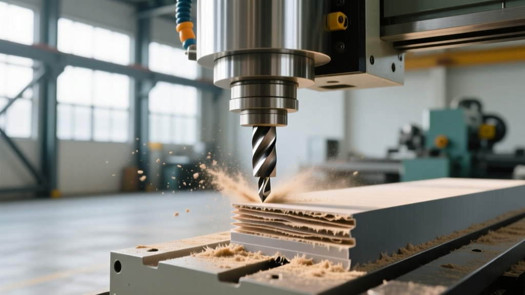
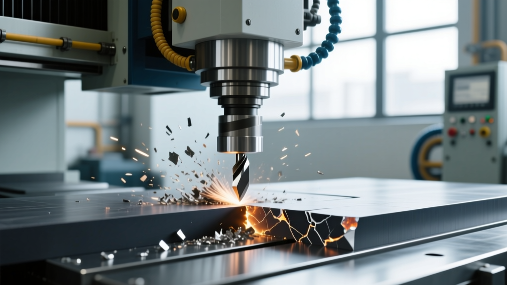
Machining carbon fiber reinforced polymers (CFRP) and glass fiber composites (GFRP) introduces severe abrasive wear and complex failure modes that standard metal-cutting setups cannot handle. When configuring a precision CNC machine for composite cutting, the primary mechanical threat is exit delamination. This occurs when the Z-axis thrust force ($F_z$) generated by the cutting tool exceeds the interlaminar fracture toughness ($G_{IC}$) of the composite layup. For standard aerospace-grade CFRP, the critical thrust force threshold is typically between 100 N and 150 N. Once this threshold is breached, the uncut plies at the exit surface push away from the spindle, causing irreversible structural separation.
To mitigate this, operators must transition from standard down-cut spirals to specialized compression routers or PCD (Polycrystalline Diamond) veined tools. Compression tools utilize a dual-helix geometry: the lower flutes pull the material upward while the upper flutes push it downward, effectively pinching the composite layers together at the shear plane and neutralizing exit thrust forces.
WARNING: Conductive Dust HazardsCarbon fiber dust is highly electrically conductive and microscopically abrasive. If ingested by the precision CNC machine's control cabinet or spindle VFD, it will cause short circuits and catastrophic electronic failure. Always verify that your machine's way covers and control enclosure seals are rated for sub-micron particulate ingress before running dry composite cuts.
Tool Geometry Selection and Wear Diagnostics
The abrasive nature of carbon and glass fibers rapidly degrades standard cutting edges. According to Harvey Tool's composite tooling documentation, tool wear in composites is measured in linear feet of cut rather than machining time. Selecting the wrong tool coating will result in exponential cost increases and scrapped parts due to fiber pull-out.
| Tool Material / Coating | Average Lifespan (CFRP) | Approx. Cost (1/2" Shank) | Best Application |
|---|---|---|---|
| Uncoated Solid Carbide | 15 - 30 linear ft | $45 - $65 | Prototyping, short-run GFRP |
| CVD Diamond Coated | 150 - 300 linear ft | $160 - $220 | Production CFRP, abrasive honeycomb |
| PCD (Polycrystalline Diamond) Veined | 1,500 - 3,000+ linear ft | $750 - $1,200+ | High-volume aerospace layups, Kevlar |
When diagnosing premature tool wear, inspect the flank face under a 20x loupe. If you observe micro-chipping along the cutting edge rather than uniform abrasive wear, your spindle may be suffering from runout. A precision CNC machine must maintain less than 0.0002 inches (5 microns) of TIR (Total Indicated Runout) at the tool nose when cutting composites; anything higher will cause the brittle diamond coatings to fracture upon initial engagement.
Troubleshooting Matrix: Symptom to Mechanical Fix
Use the following diagnostic matrix to isolate and resolve common composite cutting anomalies. This data is synthesized from Modern Machine Shop's advanced manufacturing reports on non-metallic material processing.
1. Fuzzy Edges and Fiber Pull-Out
- Root Cause: The tool is dull, or the helix angle is failing to shear the fibers cleanly, resulting in the tool 'grabbing' and tearing the resin matrix.
- Mechanical Fix: Replace the tool with a diamond-coated compression spiral. Increase the spindle RPM to 18,000–22,000 while proportionally increasing the feed rate to maintain a chip load of 0.004" to 0.006" per tooth. This ensures the material is cut, not rubbed.
2. Honeycomb Core Crushing (Aluminum or Nomex)
- Root Cause: Excessive Z-axis downforce or improper tool geometry pushing the unsupported cell walls downward before the shear plane cuts them.
- Mechanical Fix: Switch to a specialized shear-cutting router bit designed specifically for honeycomb (often featuring a high rake angle and razor-sharp uncoated carbide edge). Reduce the Z-axis plunge rate to under 50 IPM and utilize a high-speed spindle (24,000+ RPM) to slice the cell walls cleanly.
3. Workpiece Shifting During Profiling
- Root Cause: Vacuum hold-down failure. Composites are often porous or feature complex 3D contours that break the vacuum seal.
- Mechanical Fix: Verify the vacuum pump is pulling a minimum of 25 inHg (inches of mercury) at the spoilboard surface. Apply edge-sealing tape to the perimeter of the composite blank to prevent vacuum bleed-through. Surface the MDF spoilboard to a flatness tolerance of 0.002" across the entire table.
Spindle and Axis Protection in Abrasive Environments
Operating a precision CNC machine in a composite environment requires aggressive preventive maintenance. Carbon dust does not merely act as an abrasive; it acts as an electrical conductor. When carbon dust infiltrates the spindle bearings, it can facilitate Electrical Discharge Machining (EDM) damage, commonly known as bearing fluting. This occurs when stray electrical currents from the VFD pass through the bearings to the grounded machine frame, arcing across the microscopic gaps in the bearing grease.
"To prevent spindle bearing fluting in composite machining, ensure your spindle is equipped with a conductive grounding ring or carbon brush that physically contacts the spindle shaft. This provides a path of least resistance for VFD-induced shaft voltages, bypassing the bearings entirely and extending spindle life by up to 400% in abrasive environments."
Way Cover and Bellows Inspection Protocol
The linear guide blocks and ball screws on the X and Y axes are highly susceptible to composite dust ingress. Standard telescopic steel way covers often fail to seal against micro-fine carbon particles. Repair Step: Inspect the wiper seals on all linear motion blocks every 40 hours of cutting time. If carbon dust is visible on the polished rail surface, the primary labyrinth seals have failed. Upgrade to heavy-duty, multi-lip polyurethane wiper seals and switch to a high-viscosity, tacky linear guide grease (such as NSK LG2 or equivalent) that resists being washed out by aggressive dust extraction systems.
Dust Extraction and Static Dissipation Protocols
Composites generate massive volumes of hazardous, statically charged particulate. A standard 4-inch dust collection port is entirely insufficient for a 5x10-foot composite routing table.
- CFM Requirements: A precision CNC machine cutting CFRP requires a minimum of 800 to 1,200 CFM (Cubic Feet per Minute) of airflow at the cutting head to capture sub-micron particles before they become airborne.
- Static Grounding: The friction of cutting Kevlar and carbon fiber generates severe static electricity, which can cause dust to cling to the workpiece and interfere with laser tool setters. You must install a copper grounding strap connecting the workpiece, the machine table, and the dust collection hose (which must feature an internal copper wire spiral) directly to the facility's earth ground.
- Filtration: Do not use standard baghouse collectors. Composite dust requires a HEPA-filtered extraction unit with an automated pulse-jet cleaning cycle to prevent filter blinding from the fine resin particulates.
By strictly adhering to these mechanical tolerances, tooling selections, and maintenance protocols, manufacturers can eliminate the scrap rates and machine downtime that typically plague composite fabrication operations. The key to success lies in respecting the unique anisotropic properties of the material and ensuring the precision CNC machine is mechanically fortified against the extreme abrasiveness of the resulting swarf.