Controller Training for a Metal CNC Machine for Home Use
Master controller interfaces like Mach4, PathPilot, and GRBL for your metal CNC machine for home. Learn safety, probing, and troubleshooting best practices.
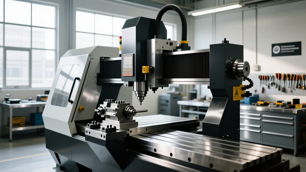
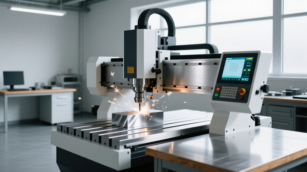
The brain of any precision milling or turning setup is its motion controller. When operating a metal CNC machine for home use—whether it is a benchtop Tormach PCNC 440, a converted Bridgeport Series 1, or a Precision Matthews PM-1030—the controller interface dictates not only your machining accuracy but your physical safety. Unlike manual machines where the operator feels the cut through handwheels, CNC operators rely entirely on software feedback loops, G-code interpretation, and hardware interfaces. Proper operator training on these systems bridges the gap between amateur hobbyist mistakes and professional-grade manufacturing.
Controller Architectures: Hobbyist vs. Prosumer
Home metal CNCs generally rely on one of three controller ecosystems. Understanding the underlying architecture is the first step in operator training, as each system handles step-pulse generation, spindle synchronization, and error handling differently.
| Controller System | Hardware Base | Approx. Cost | Best Application | Latency / Pulse Width |
|---|---|---|---|---|
| GRBL (v1.1+) | Arduino Mega 2560 / 32-bit clones | $40 - $90 | Light-duty desktop mills, plasma tables | Requires >10µs step pulse |
| Mach4 Hobby | Windows PC + Ethernet SmoothStepper (ESS) | $350 (Software + ESS) | Converted knee mills, heavy prosumer routers | Hardware generated (1-5µs capable) |
| LinuxCNC / PathPilot | Dedicated Linux PC + Mesa 7i76e FPGA cards | $150 - $300 (Mesa hardware) | Tormach mills, lathes, complex 4-axis setups | Hardware generated (sub-microsecond) |
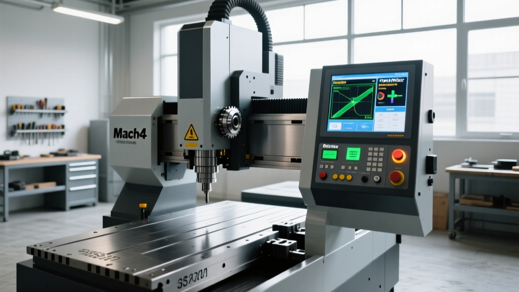
For a home machinist cutting 6061 aluminum or 1018 steel, Artisoft's Mach4 paired with an Ethernet SmoothStepper (ESS) remains a dominant choice due to its customizable screen sets and robust plugin ecosystem. However, LinuxCNC (and its commercial derivative, Tormach's PathPilot) offers superior real-time kernel performance, eliminating the micro-stutters inherent in Windows-based motion control.
Interface Ergonomics and Hardware Safety
Operator training must begin with the physical interface before a single line of G-code is executed. A common and dangerous mistake in home garage setups is relying on software-based E-stops (a red button on the monitor screen). In a true crash scenario, the Windows OS or Linux GUI may freeze, rendering a software stop useless.
WARNING: Category 0 vs. Category 1 StopsAlways wire your physical E-stop button as a Category 0 stop (immediate removal of power). The E-stop circuit must be wired in series using Normally Closed (NC) contacts directly to the VFD's (Variable Frequency Drive) enable terminal and the stepper/servo driver's enable pins. Do not route your primary E-stop solely through the controller's breakout board logic.
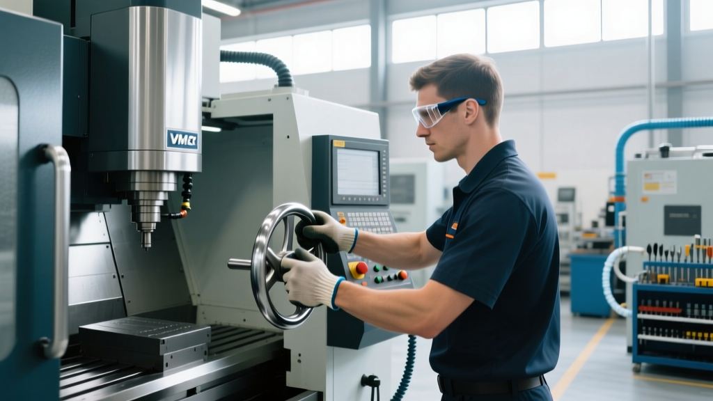
Ergonomically, the operator should never be required to use a mouse and keyboard for jogging or cycle starts. A dedicated physical pendant—such as the MPG (Manual Pulse Generator) handwheel—is mandatory. When training new operators, enforce the 'one-hand-on-pendant, one-hand-on-E-stop' rule during all tool-setting and work-coordinate probing operations.
Operator Training: Jogging and Tool Setting
Crashing a spindle into a vise is the most frequent failure mode for new CNC operators. This is rarely a software bug; it is almost always a failure in work-coordinate system (WCS) management. Training must focus heavily on the distinction between Machine Coordinates (G53) and Work Coordinates (G54-G59).
Step-by-Step: Safe Probing Cycles
While industrial shops use $3,000 Renishaw OMP600 probes, home machinists typically rely on budget CNC 3D touch probes ($80-$150) or Haimer 3D Sensors ($450). Here is the strict protocol for setting a G54 offset using a generic edge finder or touch probe in Mach4 or PathPilot:
- Clear the Z-Axis: Manually jog the Z-axis to the absolute top of travel using the MPG. Verify the Z DRO (Digital Read Out) shows a positive value relative to the machine home.
- Rough Positioning: Jog the X and Y axes over the workpiece corner. Keep the Z-axis at least 2.0 inches above the material.
- Deploy the Probe: Insert the probe into the collet. Ensure the collet is clean; a single metal chip will induce 0.002 inches of runout, ruining the probe's calibration.
- Execute the Macro: Use the controller's conversational probing screen (e.g., PathPilot's 'Set Zero' tab). Select 'Outside Corner'.
- Verify the Feed Rate: Before clicking 'Cycle Start', visually verify the probing feed rate parameter. It should not exceed 15 IPM (Inches Per Minute) for budget probes to prevent over-travel and snapping the stylus.
- Retract and Confirm: Once the probe retracts, jog the spindle 5 inches clear, then command a rapid move (G0 X0 Y0) to verify the spindle centers exactly over the probed corner.
Troubleshooting Motion Latency and Stepper Stall
When cutting steel or stainless steel on a home CNC, cutting forces are high. If the controller suffers from latency or improper pulse-width configuration, the stepper motors will stall, resulting in lost steps and scrapped parts. Operators must be trained to recognize the auditory and visual signs of controller desynchronization.
Symptom: The motor emits a high-pitched 'screaming' or 'growling' noise during rapid moves, and the tool path drifts upon return to the start point.
Root Cause: Step pulse width is too narrow for the stepper driver (e.g., DM542 or TB6600), or USB/Ethernet buffer underruns are occurring.
The Fix:
- For GRBL Users: Open the GRBL settings ($$). Increase the step pulse time ($0) from the default 10 microseconds to 15 or 20 microseconds. This gives older optocouplers on cheap stepper drivers enough time to register the pulse.
- For Mach4 / ESS Users: Open the Ethernet SmoothStepper configuration tab. Set the 'Step Pulse Width' to a minimum of 3.0 µs and the 'Direction Hold Time' to 5.0 µs. Furthermore, ensure your Ethernet cable is shielded (Cat6 S/FTP) and routed at least 12 inches away from the VFD power lines to prevent electromagnetic interference (EMI) from corrupting the data packets.
- For LinuxCNC Users: Run the
latency-testutility from the terminal. If your maximum jitter exceeds 100,000 nanoseconds (100µs) on the base thread, your PC's BIOS is interfering. Disable C-States, SpeedStep, and Hyperthreading in the BIOS to lock the CPU frequency.
Frequently Asked Questions
Can I run Mach4 or PathPilot on a Mac or a standard gaming laptop?
Mach4 requires a native Windows environment (Windows 10/11 64-bit). Running it via Parallels or Bootcamp on an Apple Silicon Mac is highly discouraged due to USB and Ethernet timing virtualization issues, which will cause erratic axis movements. PathPilot is a custom Linux distribution; it is designed to be installed bare-metal on a dedicated PC. A gaming laptop is generally overkill and often problematic due to aggressive GPU power-saving features that introduce kernel latency. A dedicated, fanless industrial mini-PC (like an Intel NUC with a Celeron or i5 processor) is the most reliable choice for a home shop.
How do I wire a VFD spindle to accept 0-10V speed control from my controller?
Most home metal CNCs use a 1.5kW to 2.2kW VFD. The controller's breakout board must output a 0-10V analog signal to the VFD's 'VI' and 'GND' terminals. Crucially, you must use a twisted-pair, shielded cable (such as Belden 8723) for this analog signal. Connect the shield to the VFD ground only at the VFD end to prevent ground loops. In the controller software, you must configure the spindle PWM frequency and map the 0-10V output to your specific RPM range (e.g., 0V = 0 RPM, 10V = 3000 RPM) using the software's spindle scaling linearization tool.
What is the best way to back up my controller configuration?
A machine crash or hard drive failure will wipe out hours of tuning, backlash compensation maps, and screen set customizations. For Mach4, navigate to the Mach4Hobby/Profiles/YourProfile folder and compress the Macros, Screen, and Plugins directories to a cloud drive weekly. For PathPilot/LinuxCNC, back up the entire ~/tmc or ~/linuxcnc/configs directory. Additionally, export your servo tuning parameters and backlash compensation tables to a physical USB drive kept in the shop's physical tool crib.