Powering the Largest CNC Machine in the World: 2026 Trends
Explore the multi-megawatt electrical requirements, harmonic mitigation, and 2026 smart-grid innovations powering the largest CNC machine in the world.
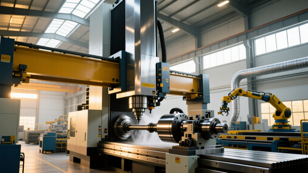
When a heavy manufacturing facility commissions the largest CNC machine in the world—such as a 40-meter-span Waldrich Siegen gantry mill or a 150-ton Ingersoll boring mill—the electrical setup is not a standard panel upgrade. It is a dedicated, substation-level infrastructure project. These ultra-large CNC machines demand multi-megawatt power feeds, advanced harmonic mitigation, and regenerative grid integration. In 2026, as aerospace and marine sectors push for larger monolithic titanium and composite structures, the electrical architecture supporting these behemoths has evolved from passive consumption to active, intelligent microgrid participation.
The Megawatt Reality: Sizing the Primary Feed
A standard 5-axis vertical machining center requires a 50 to 100 kVA electrical service. By contrast, the largest CNC machine in the world requires a dedicated 3.5 MVA to 5.0 MVA transformer feed. Calculating the exact kilovolt-ampere (kVA) requirement demands a rigorous analysis of simultaneous axis acceleration and spindle peak loads.
Load Calculation Example: 40m Gantry Mill- Main Spindle Drive: 800 kW (continuous) / 1,200 kW (peak S1 duty)
- Axis Drives (X, Y, Z, W, U): 5 x 150 kW = 750 kW
- Coolant, Hydraulics, and Chip Conveyors: 350 kW
- Total Base Load: ~1,900 kW (2.37 MVA at 0.8 power factor)
- Simultaneous Acceleration Inrush (25% buffer): 2.96 MVA
Result: A dedicated 3.0 MVA or 3.5 MVA liquid-filled transformer is required to prevent voltage sag during rapid traverse accelerations.
At 480V 3-phase, a 3.0 MVA load draws approximately 3,600 Amps. Standard molded case circuit breakers (MCCBs) top out around 2,000A to 3,000A, meaning facilities must utilize low-voltage power circuit breakers (LVPCBs) or medium-voltage switchgear stepping down directly at the machine's power distribution cabinet.
Harmonic Mitigation and IEEE 519 Compliance
Massive variable frequency drives (VFDs) powering multi-megawatt spindles and axis motors are non-linear loads. They draw current in short, high-amplitude pulses, injecting severe harmonic distortion back into the plant's electrical grid. Without mitigation, this Total Harmonic Distortion (THDi) causes transformer overheating, neutral conductor overloading, and capacitor bank resonance.
Facilities must comply with the IEEE 519-2022 Standard for Harmonic Control in Electric Power Systems, which mandates that voltage distortion (THDv) at the Point of Common Coupling (PCC) remain below 5%, and current distortion (THDi) scale according to the short-circuit ratio. For ultra-large CNC machines, achieving this requires advanced front-end drive topologies.
Decision Matrix: Passive Filters vs. Active Front Ends
| Technology | THDi Performance | Footprint | Capital Cost (Approx.) | Regeneration Capability |
|---|---|---|---|---|
| 18-Pulse Passive Transformer | 8% - 12% | Massive (requires 3-winding phase-shifting transformer) | $85,000 - $120,000 | No (Requires braking resistors) |
| Active Harmonic Filters (AHF) | < 5% (Injects opposing current) | Medium (Parallel cabinet) | $110,000 - $150,000 | No |
| Active Front End (AFE) Drive | < 3% (Sinusoidal grid current) | Integrated into main drive cabinet | $180,000 - $220,000 | Yes (Bi-directional power flow) |
For the largest CNC machines in the world, the Active Front End (AFE) is the definitive standard in 2026. AFEs use IGBT-based rectifiers to draw sinusoidal current from the grid, virtually eliminating harmonics at the source while enabling regenerative braking.
2026 Innovations: Regenerative Braking and Microgrids
When a 120-ton crossrail or a massive 80-ton rotary table decelerates from rapid traverse speeds, the kinetic energy must be dissipated. Historically, this was burned off as waste heat through massive banks of dynamic braking resistors, requiring dedicated HVAC cooling just to manage the resistor room.
Modern ultra-large CNC setups utilize regenerative DC bus architectures coupled with bidirectional grid-tie inverters. According to data tracked by the U.S. Department of Energy Advanced Manufacturing Office, capturing regenerative energy from heavy industrial drives can reduce overall motor system energy consumption by up to 15% in high-inertia applications.
Pro-Tip: Microgrid IntegrationInstead of feeding regenerated power directly back to the utility grid (which often incurs strict utility interconnection fees and power factor penalties), route the AFE output to a localized plant DC microgrid. This DC bus can directly power auxiliary systems like the machine's 200 HP high-pressure coolant pumps and hydraulic power units, bypassing AC/DC conversion losses and yielding up to $140,000 in annual energy savings for 24/7 operations.
Cable Routing, Voltage Drop, and Thermal Management
Routing 3,600 Amps of 480V power from the substation to the machine's main disconnect requires meticulous engineering. Standard cable trays are insufficient due to the weight and bending radius of 500 MCM or 750 MCM THHN copper conductors.
- Busway Systems: Most tier-one aerospace facilities now utilize 4,000A rated enclosed busway systems (e.g., Siemens Sentron or Schneider Canalis). Busways offer lower impedance, reducing voltage drop to less than 1.5% over a 400-foot run, which is critical for maintaining the strict voltage tolerances required by precision spindle drives.
- Thermal Imaging: At 3,000+ Amps, even a micro-ohm of loose connection resistance generates immense heat. All busway joints and LVPCB lugs must be torqued to exact manufacturer specifications and verified with ultrasonic and infrared thermography during the first 30 days of operation.
Control Voltage Redundancy and Industrial UPS
The largest CNC machine in the world features hundreds of distributed I/O nodes, safety PLCs (such as Siemens Safety Integrated), and high-resolution linear encoders. A 10-millisecond voltage sag or brownout on the 480V grid can cause the main controller to fault, crashing a 150-ton spindle into a $5,000,000 titanium aerospace forging.
To prevent this, the control architecture must be entirely isolated from the power drive architecture:
- Isolation Transformer: A dedicated 150 kVA delta-wye isolation transformer feeds only the control cabinets, providing a separately derived neutral and blocking common-mode noise from the VFDs.
- Redundant 24VDC Supplies: Utilize redundant, load-sharing 24VDC power supplies (e.g., Phoenix Contact QUINT or Siemens SITOP) with active MOSFET decoupling modules to ensure a single power supply failure does not drop the safety logic.
- Industrial UPS: A 20 kVA online, double-conversion Uninterruptible Power Supply (UPS) with lithium-iron-phosphate (LiFePO4) battery modules must be installed. This provides ride-through capability for the CNC controller, allowing the machine to execute a safe, controlled retraction of the spindle and engage mechanical axis brakes during a total facility blackout.
Step-by-Step Electrical Commissioning Protocol
Commissioning a multi-megawatt CNC machine requires a phased approach to prevent catastrophic equipment damage. Do not energize the main drive bus until the following sequence is validated:
CRITICAL WARNING: Inrush Current PenaltiesEnergizing a 3.5 MVA transformer without pre-magnetization or soft-start protocols will generate an inrush current exceeding 25,000 Amps for up to 10 cycles. This will trip upstream utility relays and may result in severe demand ratchet penalties from your local power provider. Always use a resistor-based pre-charge circuit or medium-voltage soft-start for the primary transformer.
- Megger and Hi-Pot Testing (Days 1-2): Perform insulation resistance testing on all 480V busways and motor windings at 1,000V DC. Minimum acceptable resistance is 100 Megohms. Follow with VLF (Very Low Frequency) hi-pot testing on the medium-voltage feed cables.
- Control Loop Validation (Days 3-5): Energize only the 120V/24V control circuits. Verify all safety interlocks, E-stop chains, and limit switches using the PLC diagnostic screens before any high voltage is introduced.
- Drive Auto-Tuning and Phasing (Days 6-8): Power the VFDs and perform static and dynamic auto-tuning routines. Verify motor phasing with a rotation meter; running a 1,000 HP spindle motor in reverse for even three seconds can destroy the ceramic hybrid bearings and the spindle drawbar mechanism.
- Harmonic Spectrum Analysis (Day 10): Under full-load cutting conditions, use a Fluke 435-II or Dranetz power quality analyzer at the PCC to verify THDv remains below 5% and that no resonant frequencies are exciting the plant's power factor correction capacitors.
Engineering the electrical infrastructure for the largest CNC machine in the world requires moving beyond standard NEC code minimums. By implementing Active Front Ends, regenerative DC microgrids, and redundant control architectures, modern heavy manufacturing facilities ensure these massive assets deliver decades of uninterrupted, high-precision production.