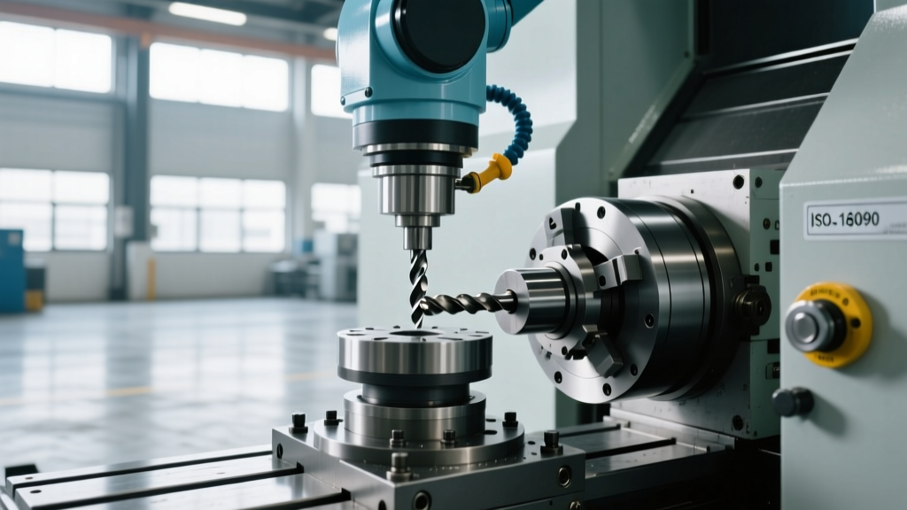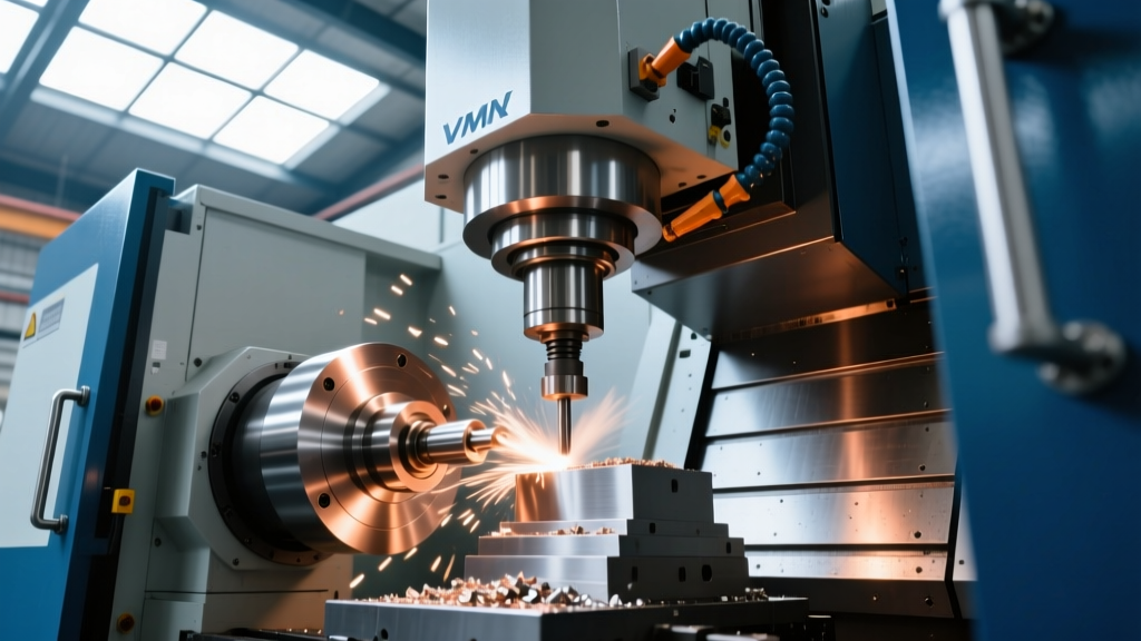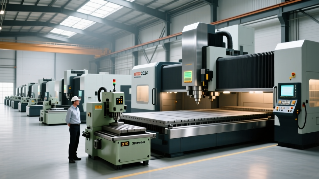
History of CNC Machines: Evolution of Bed Sizes and Work Envelopes
Explore the history of CNC machines through the evolution of bed sizes and work envelopes, comparing early models to modern 5-axis machining centers.
When examining the history of CNC machines, most industry narratives focus heavily on control systems—from early punched tape to modern AI-driven adaptive toolpaths. However, the physical evolution of the machine bed size and work envelope tells an equally critical story of manufacturing innovation. The spatial capabilities of machining centers have dictated part complexity, production throughput, and the very architecture of modern supply chains. Understanding how work envelopes have expanded, contracted, and morphed over the decades is essential for manufacturing engineers making capital equipment investments in 2026.
Defining the Metrics: Bed Size vs. Work EnvelopeBed Size (Table Footprint): The physical X-Y dimensions of the machine table available for workholding, vises, or tombstones.
Work Envelope: The maximum 3D volumetric space (X, Y, Z travels) the spindle nose or tool tip can physically reach.
Critical Distinction: A massive bed size does not guarantee a proportionate Z-axis envelope. In modern 5-axis configurations, adding rotary axes often drastically reduces the usable Z-height compared to a 3-axis machine with the same physical footprint.
The Parsons Era: Early Spatial Limitations and Retrofit Envelopes
The genesis of numerical control traces back to John Parsons and the MIT Servomechanisms Laboratory in the late 1940s and 1950s. Early CNC machines were not built from scratch; they were heavily modified manual knee mills, such as the Cincinnati Milacron Hydrotel. Because these machines relied on the existing castings of manual mills, their work envelopes were severely restricted by the physical limits of the knee-and-column design.
In these early models, the Y-axis and Z-axis were often coupled to the same moving column or knee, leading to massive deflection under heavy cutting loads. The usable work envelope was effectively a fraction of the advertised travel, as pushing the spindle to the extreme edges of the X-Y bed resulted in unacceptable chatter and tool breakage. It was not until the introduction of the fixed-column, moving-bed Vertical Machining Center (VMC) architecture in the 1970s and 1980s that the work envelope became a rigid, predictable volumetric space.
The VMC Revolution: Standardizing the 40-Taper Envelope
As the history of CNC machines progressed into the 1980s and 1990s, the industry demanded standardized work envelopes that matched the most common aerospace and automotive prismatic parts. This era birthed the ubiquitous 40-taper VMC. Companies like Haas Automation and Mazak pioneered the mass production of VMCs with highly predictable bed-to-envelope ratios.
The standard "20-by-40" machine became the industry benchmark. A table size of roughly 40 inches by 20 inches yielded a work envelope of approximately 30" x 20" x 20". This specific geometry was not arbitrary; it was engineered to accommodate standard 6-inch milling vises placed side-by-side, allowing operators to machine a part in one vise while loading raw material in the other, maximizing spindle uptime.
Decade-by-Decade Expansion of Standard VMC Envelopes
| Era | Standard Bed Size (X-Y) | Typical Work Envelope (X-Y-Z) | Dominant Application |
|---|---|---|---|
| 1970s (Knee Mills) | 9" x 42" (Table) | 20" x 12" x 16" | Manual-to-NC retrofits, light 2.5D milling |
| 1990s (Early VMCs) | 36" x 14" | 30" x 20" x 20" | Standard prismatic parts, mold bases |
| 2010s (High-Speed VMCs) | 44" x 20" | 40" x 26" x 24" | Aerospace structural components, multi-part fixturing |
| 2026 (Automated Cells) | 60" x 30"+ | 50" x 26" x 25" (with automated pallet changers) | Lights-out manufacturing, large titanium aerospace forgings |
The 5-Axis Paradox: Shrinking the Usable Envelope
One of the most vital lessons in the history of CNC machines is the spatial cost of multi-axis kinematics. When the industry transitioned from 3-axis to 5-axis simultaneous machining, the physical footprint of the machines often remained similar, but the usable work envelope shrank dramatically.
Consider a standard 3-axis VMC with a 20-inch Z-axis travel. If you mount a traditional A-axis/C-axis trunnion table onto that bed to achieve 5-axis capability, the trunnion itself consumes 6 to 8 inches of Z-height. Furthermore, the tool length and the distance required to rotate the part without colliding with the machine column further erode the Z-axis. Consequently, a machine that previously machined 15-inch-tall blocks may now only safely accommodate 6-inch-tall parts in a 5-axis configuration.
Trunnion vs. Swivel Head: Spatial Trade-offs
To combat envelope shrinkage, machine builders diverged into two primary kinematic designs:
- Table-Trunnion (e.g., DMG MORI DMU 50 3rd Gen): The rotary axes are integrated into the table. This provides superior undercut capabilities and high rigidity for heavy metals like Inconel, but it heavily penalizes the Z-axis envelope and limits maximum part weight due to the cantilevered nature of the rotating table.
- Swivel-Head (e.g., Mazak VARIAXIS series): The B-axis and C-axis are housed in the spindle head, while the table only handles linear X-Y movements (or a simple rotary C-axis). This preserves the massive Z-axis envelope required for deep mold cavities and aerospace spars, but introduces dynamic deflection challenges at the spindle nose during heavy roughing.
2026 Trends: Thermal Growth and Gantry Extremes
As we navigate the manufacturing landscape of 2026, the push toward both micro-machining and massive monolithic aerospace structures has bifurcated work envelope engineering. According to research tracked by NIST's Advanced Manufacturing programs, managing thermal distortion within large work envelopes is now the primary limiting factor in machine accuracy, superseding static geometric errors.
"In large-format gantry mills with Y-axis travels exceeding 3 meters, a mere 3°C ambient shop floor gradient can induce up to 100 microns of thermal yaw. Modern machine builders are no longer just selling a physical work envelope; they are selling active thermal compensation algorithms and liquid-cooled castings that guarantee the envelope remains geometrically stable regardless of the time of day."
At the opposite extreme, micro-machining centers from builders like Willemin-Macodel operate in envelopes smaller than a standard shoebox (e.g., 200mm x 200mm x 200mm). In these ultra-compact spaces, the challenge is not structural deflection, but accommodating the necessary tool changers, high-pressure coolant nozzles, and optical inspection cameras without causing tool-to-fixture collisions. The trend in 2026 is toward "dense envelopes," where the ratio of machine footprint to usable work volume is optimized through linear motor drives and stacked tool magazines.
Decision Framework: Matching Part Geometry to Envelope Evolution
When specifying a new CNC machine, purchasing agents and manufacturing engineers must look past the marketing brochure's "Table Size" and rigorously audit the true volumetric envelope. Use the following framework to avoid costly spatial miscalculations:
- Map the Swept Volume, Not Just the Part Size: A 10-inch diameter part requires significantly more than 10 inches of X-Y travel when factoring in the tool radius, toolholder clearance, and the swept arc of the cutter. Always add a minimum of 15% to the maximum part dimension to calculate the required linear travel.
- Audit the Z-Axis Penalty for Automation: If you plan to integrate a zero-point clamping system (like System 3R or Schunk) or a robotic pallet changer, subtract 4 to 6 inches from the machine's advertised Z-axis travel immediately. Ensure the remaining Z-height accommodates your tallest part plus 2 inches of tool clearance.
- Verify the ATC Swing Radius: In compact 5-axis machines, the Automatic Tool Changer (ATC) arm often swings into the work envelope. If you are utilizing a tall tombstone or a large trunnion fixture, verify the machine's "ATC interference zone" in the controller's kinematic simulation before finalizing the purchase.
- Demand Volumetric Accuracy Data: For machines with X-axis travels over 50 inches, require the builder to provide a laser interferometer and ballbar test report specifically detailing volumetric diagonal accuracy (ISO 230-6), not just linear axis positioning. A massive bed is useless if the center of the envelope sags by 50 microns under the weight of a heavy casting.
The history of CNC machines proves that the work envelope is not a static box, but a dynamic, engineered environment. By understanding the kinematic trade-offs and thermal realities that define modern machine geometry, manufacturers can align their capital investments precisely with their production realities.