CNC Machine vs 3D Printer: Spindle Speed & Feed Rate Optimization
Compare CNC machine vs 3D printer capabilities by mastering spindle speed and feed rate optimization for superior tolerances and cycle times.
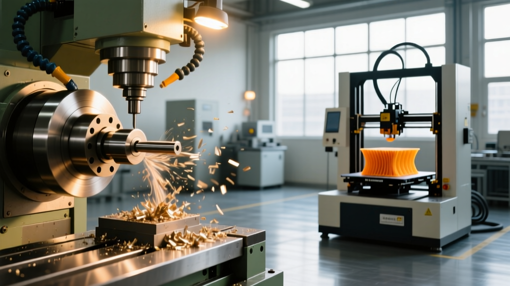
The engineering debate surrounding a CNC machine vs 3D printer often devolves into superficial comparisons of upfront cost or software ease-of-use. True manufacturing engineers evaluate the fundamental kinematics: subtractive material removal governed by spindle speed and feed rate, versus additive material deposition governed by extrusion flow and layer height. Understanding how to optimize CNC spindle speeds and feed rates is the definitive factor that allows subtractive manufacturing to achieve the surface finishes, tight tolerances, and volumetric throughput rates that additive systems simply cannot replicate in functional metal and engineering-grade plastic parts.
The Kinematics Divide: Rotational Subtraction vs. Linear Extrusion
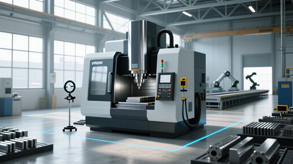
CNC machining relies on rotational kinetic energy transferred through a rigid spindle to a cutting tool, shearing material away in the form of chips. In 2026, standard vertical machining centers (VMCs) utilize direct-drive or belt-driven spindles ranging from 8,000 to 15,000 RPM, with high-speed machining (HSM) centers pushing 24,000 to 42,000 RPM via HSK-63A or HSK-E40 toolholders. The rigidity of the cast-iron or polymer-concrete frame absorbs the harmonic vibrations generated during heavy material removal.
Conversely, Fused Deposition Modeling (FDM) 3D printers rely on NEMA 17 or NEMA 23 stepper motors driving linear belts or lead screws to deposit molten polymer. The kinematic limits of an FDM printer are bound by the volumetric flow rate of the hotend (typically 15 to 35 cubic millimeters per second for standard 0.4mm nozzles) and the thermal cooling limits of the part. While 3D printers excel at complex internal lattices, they lack the shear force capability to produce high-strength, fully dense metal parts without secondary sintering processes.
⚠️ The Tolerance Reality Check: A properly optimized CNC milling operation holding a 1/2" bore diameter will consistently achieve a geometric tolerance of ±0.0005" with a surface roughness (Ra) of 32 μin. An industrial FDM 3D printer printing the same feature in ABS or PETG will yield a tolerance of ±0.010" to ±0.020" due to thermal shrinkage, stepper motor microstepping variance, and layer-shifting artifacts.CNC Spindle Speed and Feed Rate Optimization: The Mathematics
To leverage the full capability of a CNC machine over a 3D printer, operators must move beyond conservative, generic CAM defaults and calculate exact cutting parameters based on tool geometry, coating, and material hardness. According to Sandvik Coromant's milling formulas, optimizing these variables prevents tool deflection, work hardening, and catastrophic tool failure.
Calculating Surface Speed (SFM) and RPM
Surface Feet per Minute (SFM) represents the speed at which the cutting edge engages the material. For a 1/2" (0.500") diameter, 3-flute AlTiN-coated carbide end mill cutting 6061-T6 Aluminum, the recommended SFM is approximately 1,200. The formula to translate SFM into Spindle RPM is:
RPM = (SFM × 3.82) / Tool Diameter
- RPM = (1,200 × 3.82) / 0.500
- RPM = 9,168
Running the spindle at 9,168 RPM ensures the carbide cutting edges operate within their optimal thermal window, allowing the AlTiN coating to form a protective aluminum oxide layer that resists abrasive wear.
Dialing in Chip Load (IPT) and Feed Rate
Chip load, or Inches Per Tooth (IPT), is the thickness of the material removed by each flute per revolution. Harvey Tool's speeds and feeds guidelines suggest an IPT of 0.004" for a 1/2" carbide end mill in aluminum. If the chip load is too low, the tool rubs instead of cutting, generating excessive heat and accelerating flank wear. The Feed Rate (Inches Per Minute, IPM) is calculated as:
Feed Rate = RPM × Number of Flutes × Chip Load
- Feed Rate = 9,168 × 3 × 0.004
- Feed Rate = 110 IPM
Volumetric Throughput: CNC MRR vs. 3D Printer Flow Rate
The most stark contrast in the CNC machine vs 3D printer comparison is the Material Removal Rate (MRR) versus the Additive Volumetric Flow Rate. Let us compare the machining of a 6061-T6 aluminum bracket to printing the same volume in PETG.
| Metric | CNC Milling (6061-T6) | FDM 3D Printing (PETG) |
|---|---|---|
| Process Parameter | 0.25" RDOC, 0.5" ADOC, 110 IPM | 0.4mm Nozzle, 0.2mm Layer, 60 mm/s |
| Volumetric Throughput | 13.75 in³/min (225 cm³/min) | 0.017 in³/min (0.29 cm³/min) |
| Surface Finish (Ra) | 32 - 64 μin | 250 - 400 μin (Layer lines visible) |
| Isotropic Strength | 100% (Homogeneous grain structure) | ~60% on Z-axis (Layer adhesion limits) |
As demonstrated, the CNC machine removes material nearly 800 times faster than the FDM printer adds it. Furthermore, the CNC part exhibits isotropic material properties, meaning its tensile and yield strength are uniform in all axes. The 3D printed part suffers from Z-axis weakness due to the thermal bonding limits between extruded layers.
Toolpath Engagement vs. Additive Slicing Algorithms
Optimizing feed rates in modern CAM software (like Mastercam or Fusion 360) involves utilizing Adaptive Clearing or Trochoidal Milling toolpaths. These algorithms maintain a constant radial engagement angle (typically 10% to 15% of the tool diameter) while allowing the axial depth of cut to increase up to 2x the tool diameter. This permits feed rates to be increased by 200% to 300% while keeping cutting forces and spindle load perfectly stable.
In contrast, 3D printer slicers (like PrusaSlicer or Cura) manage complexity through infill patterns (gyroid, rectilinear, cubic). While a gyroid infill provides excellent multi-directional support, the print head must constantly accelerate and decelerate to navigate the intricate geometry. This introduces ringing artifacts (ghosting) on the external walls and limits the maximum volumetric flow rate of the hotend, further widening the cycle-time gap between the two technologies.
Expert Insight: When machining high-temperature alloys like Inconel 718, spindle speed optimization flips. Instead of high RPM, operators drop the SFM to 60-80 and utilize high-torque, low-RPM spindles (2,000 - 3,500 RPM) paired with ceramic end mills. No FDM or SLA 3D printer can process Inconel directly; they must rely on indirect metal binder jetting or DMLS, which require extensive support structures and post-print HIP (Hot Isostatic Pressing) treatments.
Decision Framework: When Kinematics Dictate the Process
Selecting between a CNC machine and a 3D printer requires analyzing the specific physical demands of the end-use part. Referencing data from NIST's Additive Manufacturing programs regarding AM qualification standards, here is the definitive framework for process selection:
- Choose CNC Machining When: The part requires tight geometric tolerances (±0.001" or tighter), flawless surface finishes for sealing surfaces (O-ring grooves), high cyclic fatigue resistance, or is machined from wrought metals (Aluminum, Steel, Titanium, Brass).
- Choose 3D Printing When: The part features internal conformal cooling channels, complex topology-optimized organic shapes that are impossible to reach with a 5-axis CNC spindle, or when producing low-volume jigs and fixtures where lead time outweighs structural integrity.
Frequently Asked Questions
Can a 3D printer match the surface finish of an optimized CNC feed rate?
No. Even high-resolution SLA (Stereolithography) resin printers produce a surface roughness (Ra) of roughly 64 to 125 μin due to the meniscus effect of the resin meniscus and laser spot overlap. A CNC machine running a finish pass with a high-feed, low-RDOC parameter using a polished carbide ballnose end mill can achieve an Ra of 16 μin or better, which is mirror-smooth and requires no secondary sanding or vapor smoothing.
How does spindle runout affect CNC feed rate optimization?
Spindle runout is the microscopic wobble of the tool holder. If a spindle has 0.0003" of runout, the cutting flutes do not share the chip load equally. One flute will take 80% of the load and chip prematurely, while the other rubs. To maintain optimized feed rates, high-precision hydraulic or shrink-fit toolholders must be used to keep runout below 0.0001", ensuring the calculated IPT is perfectly distributed across all flutes.
Are hybrid CNC-3D printer machines viable for production?
Hybrid machines that combine wire-arc additive manufacturing (WAAM) or laser metal deposition (DED) with a CNC milling spindle exist, but they are highly specialized and cost upwards of $500,000. They are used primarily for repairing expensive turbine blades or adding localized features to large castings, rather than general-purpose prototyping where standalone CNC and 3D printing units remain vastly more economical and efficient.