CNC Screw Machine Controller Interfaces: Training Guide
Master CNC screw machine controller interfaces. This training guide covers Fanuc and Mitsubishi screens, setup best practices, and crash prevention.
The Cognitive Load of Modern CNC Screw Machine Interfaces
The term 'CNC screw machine' encompasses a highly specialized class of automatic lathes—primarily Swiss-type and multi-spindle turning centers—designed for high-volume, tight-tolerance production. While legacy mechanical screw machines relied on physical cams and drum switches, modern CNC screw machines operate via complex, multi-channel digital interfaces. For shop floor managers and lead machinists, operator training on these specific controller types is not merely about teaching G-code; it is about mastering the proprietary user interfaces (UIs) that govern sub-spindle synchronization, guide bushing offsets, and overlapping toolpaths.
According to industry training standards outlined by the Society of Manufacturing Engineers (SME), the leading cause of catastrophic crashes on Swiss-type lathes is not incorrect CAM programming, but rather operator error during manual offset entry and interface navigation on the shop floor. This guide details the dominant controller architectures found on modern CNC screw machines and provides actionable training frameworks for safe, efficient operation.
⚠️ Financial Impact Warning: A main spindle crash on a typical 20mm or 32mm capacity Swiss-type CNC screw machine requires complete spindle rebuild or replacement. In 2026, OEM spindle replacement costs range from $22,000 to $38,000, excluding machine downtime and secondary damage to the guide bushing or sub-spindle tooling.Core Controller Architectures in Swiss-Type and Multi-Spindle Machines
Unlike standard 3-axis vertical machining centers that often use generic conversational controls, CNC screw machines demand controllers capable of managing 7 to 13+ simultaneous axes across multiple channels. The market is dominated by two primary hardware providers, often wrapped in OEM-specific software layers.
Fanuc 31i-B5 and 32i-B5 (The Industry Standard)
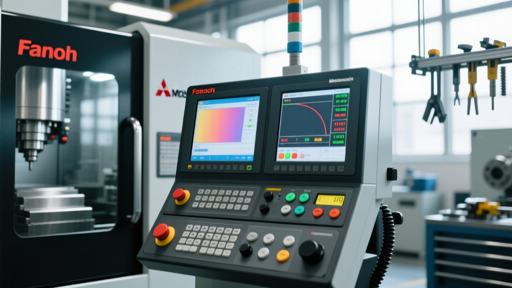
The Fanuc 31i-B5 is the undisputed workhorse of the CNC screw machine sector, powering the majority of Citizen Cincom, Star Micronics, and Tsugami models. Training operators on the Fanuc interface requires deep familiarity with its dual-screen capabilities and channel management.
- Channel Switching: Operators must be trained to use the physical 'CH1' and 'CH2' soft keys or the dedicated channel-select button on the machine operation panel (MOP). A common training failure occurs when an operator adjusts the tool offset in Channel 1 while the machine is actively cutting in Channel 2, leading to immediate collisions.
- Nanometer Interpolation Display: The 31i-B5 displays positions in nanometers (e.g., X10.000500). Operators must be trained to read the 4th and 5th decimal places accurately when verifying guide bushing clearance, rather than truncating to standard 3-decimal millimeter or 4-decimal inch formats.
- Macro Variable Access: Advanced operators need access to the #500 series macro variables (e.g., #501 for main spindle load monitoring) to implement custom alarm conditions for tool breakage detection.
Mitsubishi M800/M80 Series (High-Speed Precision)
Often found on Nakamura-Tome and select Tornos multi-spindle CNC screw machines, the Mitsubishi M80 series utilizes a completely different UI paradigm, heavily reliant on capacitive touchscreens and optical communication buses.
- Touchscreen Tool Data Management: The M80 interface allows operators to drag-and-drop tool icons into the turret map. Training must emphasize the 'Tool Life Management' screen, where operators input part-count limits rather than time limits, ensuring the machine triggers a sister-tool replacement exactly when the cutting edge degrades.
- SSS (Super Smooth Surface) Control: Operators must know how to toggle SSS parameters on the 'Machining Parameter' screen to dynamically adjust acceleration/deceleration constants based on the specific material being turned (e.g., 303 Stainless vs. 6061 Aluminum).
OEM Proprietary Overlays (Citizen, Star, Tsugami)
To bridge the gap between raw Fanuc/Mitsubishi hardware and the specific kinematics of their machines, OEMs build proprietary conversational layers. For example, Citizen's proprietary interface abstracts complex C-axis and Y-axis milling routines into simple fill-in-the-blank screens. Operators must be trained to verify the 'G-code Output' preview screen before executing, as the proprietary generator occasionally misinterprets complex polar interpolation commands.
Controller Comparison and Training Focus Matrix
Use the following matrix to structure your cross-training program based on the specific CNC screw machine controllers present on your floor.
| Controller Model | Primary OEM Integration | Key Interface Feature | Operator Learning Curve | Critical Training Focus |
|---|---|---|---|---|
| Fanuc 31i-B5 | Star, Tsugami, Citizen | Dual-channel simultaneous execution | High (4-6 weeks) | Channel isolation & G50 shifting |
| Mitsubishi M80 | Nakamura-Tome, Tornos | Touch-driven tool life management | Medium (2-4 weeks) | Sister-tool mapping & SSS toggles |
| Siemens Sinumerik 840D sl | Index, Traub | ShopTurn conversational GUI | Low-Medium (2-3 weeks) | Parametric programming & collision avoidance |
Best Practices for Safe Interface Navigation and Offset Entry
The most dangerous moment in CNC screw machine operation is the first-part setup and mid-shift tool wear offset adjustment. Implement the following strict UI navigation protocols during operator training.
The 'Three-Screen Verification' Protocol
Before pressing cycle start after entering a new tool offset, operators must be trained to cycle through three specific screens:
- The Offset Screen (OFS/SET): Verify the geometry offset (e.g., U and W values) matches the physical tool presetter data. Ensure the wear offset is zeroed out for a new insert.
- The Absolute Position Screen (POS -> ABS): Check the current distance-to-go. On a Swiss-type machine, verify that the Z-axis absolute position accounts for the guide bushing thickness and the specific collet depth.
- The Program Check Screen (PRGRM -> CHECK): Run the graphical toolpath simulation. Operators must be trained to look specifically for the sub-spindle pick-off phase, ensuring the Z-axis clearance between the main and sub-spindle chucks remains positive during the transfer.
On Fanuc-controlled CNC screw machines, teach operators the difference between standard tool offsets and the G50 coordinate shift command. G50 shifts the entire coordinate system and is frequently used to compensate for thermal growth in the guide bushing over a 12-hour shift. Misunderstanding G50 is a primary cause of Z-axis over-travel alarms.
Troubleshooting Common Interface Alarms: A Decision Tree
Operators must be trained to read the controller's alarm history screen (ALM -> HST) rather than simply hitting the reset button. Below is a training framework for the three most common CNC screw machine interface alarms.
1. Servo Error / Overload Alarms (e.g., Fanuc Alarm 411 or 431)
- Cause: The main spindle or C-axis servo motor is drawing excessive current.
- Interface Check: Navigate to the 'Diagnosis' (DGNOS) screen. Check parameters #700 to #709 for spindle load percentage.
- Action: If load exceeds 85% during roughing, the operator must reduce the depth of cut (DOC) via the override switch or adjust the feedrate in the CAM program. Do not simply increase the servo alarm threshold in the parameters.
2. Sub-Spindle Synchronization Alarms
- Cause: The main and sub-spindle RPMs do not match within the required tolerance during the part pick-off phase.
- Interface Check: View the 'Spindle Monitor' screen. Look for the phase difference (in degrees) between Spindle 1 and Spindle 2.
- Action: Clean the spindle encoder glass. If the phase error persists, the operator must notify maintenance to recalibrate the spindle orientation parameter (often Fanuc parameter #4077).
3. Parameter Write Enable (PWE) Alarms (e.g., Fanuc Alarm 100)
- Cause: An operator or setup technician left the PWE switch set to '1' (enabled) after modifying macro variables or tool data.
- Interface Check: The alarm screen will explicitly state PWE is active.
- Action: Set PWE back to '0' immediately. Train operators that leaving PWE enabled allows accidental overwriting of critical kinematic parameters, which can permanently destroy the machine's geometric accuracy.
Simulation and Virtual Training Environments
Physical machine time on a CNC screw machine is too valuable to use for basic interface familiarization. Modern training programs utilize digital twins and offline simulation. Software platforms like CNC Simulator Pro or OEM-specific CAM integrations (such as ESPRIT for Swiss) replicate the exact Fanuc or Mitsubishi UI on a desktop monitor.
According to Fanuc America's educational resources, utilizing their standalone CNC Guide software allows operators to practice soft-key navigation, macro variable editing, and alarm resetting in a zero-risk environment. A standard training protocol requires 20 hours of simulated UI navigation—specifically focusing on tool offset entry and sub-spindle synchronization setup—before an operator is cleared to touch the physical machine operation panel.
"The interface on a multi-spindle CNC screw machine is essentially an air traffic control tower. The operator isn't just driving one tool; they are managing the timing and clearance of twelve independent tools operating in a space the size of a matchbox. UI fluency is just as critical as metrology skills." — Lead Manufacturing Engineer, Precision Medical Components Sector
Frequently Asked Questions (FAQ)
Can an operator trained on standard VMC controllers run a CNC screw machine?
No. Standard 3-axis VMC controllers (like the Haas NGC or standard Fanuc 0i-F) lack the multi-channel architecture, guide bushing kinematics, and sub-spindle synchronization screens required for screw machines. A VMC operator requires a minimum of 40 hours of targeted cross-training on Swiss-type interface navigation before operating independently.
How do we prevent operators from bypassing safety interlocks via the interface?
Utilize the controller's 'Operator Lock' or 'Custom Screen' features. On Fanuc 31i controls, you can password-protect specific parameter pages and restrict the 'Single Block' and 'Block Delete' toggles to supervisor-level access codes, ensuring operators cannot accidentally skip critical safety blocks during high-volume production runs.