CNC Machine Tooling Maintenance: Dust & Chip Management Schedules
Optimize your maintenance schedule with our guide to CNC dust collection and chip management to protect CNC machine tooling and extend spindle life.
The Hidden Cost of Particulate Ingress on CNC Machine Tooling
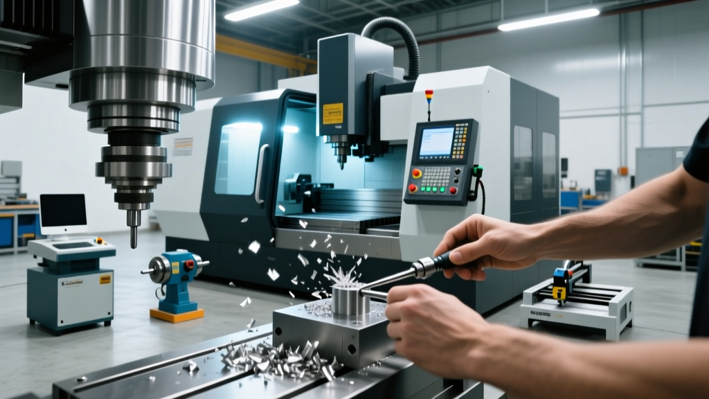
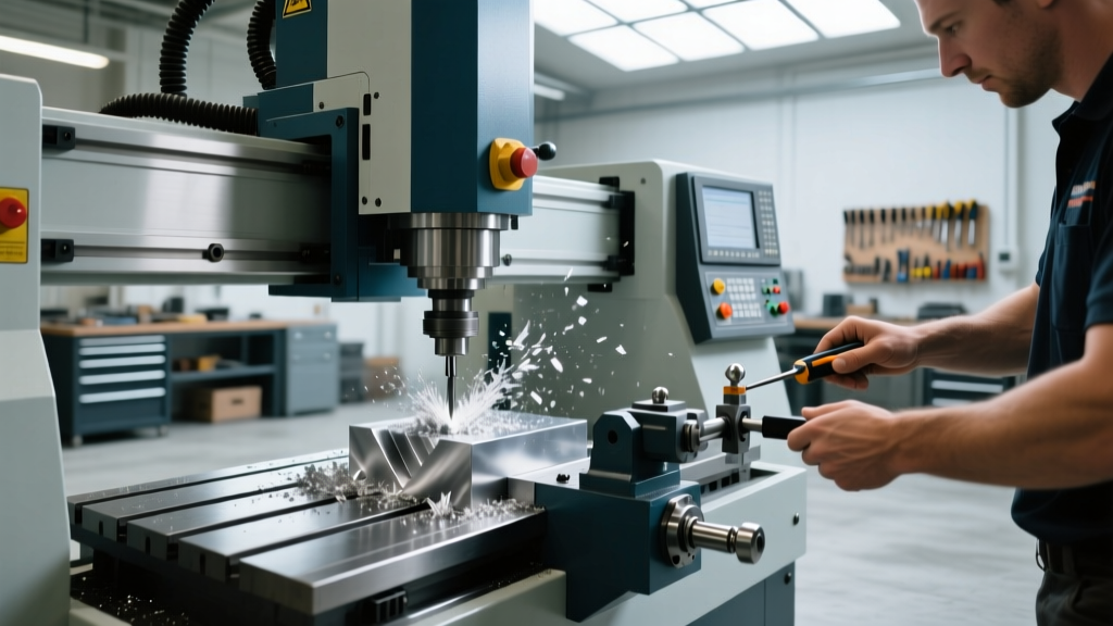
Modern manufacturing environments demand extreme precision, yet the most critical threat to machining accuracy often originates from the byproduct of the cutting process itself. Swarf, abrasive dust, and aerosolized coolant mist are not merely housekeeping nuisances; they are active agents of mechanical degradation. When extraction systems fail or fall behind maintenance schedules, micron-level particulates bypass way covers and infiltrate spindle tapers. For high-precision CNC machine tooling, particularly dual-contact interfaces like HSK63A or BIG-PLUS BT40, even 0.0002 in. of embedded dust on the toolholder taper causes severe Total Indicated Runout (TIR). This runout accelerates carbide insert wear by up to 45% and induces chatter that destroys surface finish tolerances.
Effective dust collection and chip management must be treated as a core pillar of your preventative maintenance (PM) program, not an afterthought. As of 2026, with the widespread adoption of nanocoated end mills and high-speed spindles exceeding 20,000 RPM, the financial justification for rigorous extraction maintenance is undeniable. Replacing a set of degraded linear guideway blocks costs between $1,200 and $2,500, whereas a proactive annual filtration and conveyor service rarely exceeds $400 per machine.
Critical Alert: According to OSHA guidelines on combustible dust, accumulated aluminum, titanium, or magnesium swarf in dry chip bins presents a severe deflagration hazard. Extraction maintenance is simultaneously a tooling preservation strategy and a critical safety compliance requirement.Engineering the Extraction: CFM and Static Pressure Matrix
Sizing and maintaining a dust collector requires understanding the aerodynamic demands of your specific machine enclosure. A common failure mode in maintenance schedules is ignoring static pressure drops across dirty filters, which starves the enclosure of necessary Cubic Feet per Minute (CFM) airflow. Below is the baseline engineering matrix for maintaining optimal negative pressure in standard CNC environments.
| Machine Type | Enclosure Volume | Target CFM | Required Static Pressure | Primary Contaminant |
|---|---|---|---|---|
| Vertical Machining Center (VMC) | 150 - 250 cu ft | 800 - 1,200 | 10 - 12 in. w.g. | Oil mist, fine cast iron dust |
| CNC Turning Center | 100 - 180 cu ft | 600 - 900 | 8 - 10 in. w.g. | Heavy wet chips, coolant vapor |
| 5-Axis Simultaneous Mill | 250 - 400 cu ft | 1,200 - 1,800 | 12 - 15 in. w.g. | Aerosolized mist, micro-swarf |
| CNC Router (Wood/Plastics) | Open / Partial | 1,500 - 3,000 | 14 - 18 in. w.g. | Combustible dry dust, static |
Note: Static pressure is measured in inches of water gauge (in. w.g.). Maintenance teams must log manometer readings weekly to track filter loading.
Filter Media Selection and Pulse-Jet Maintenance
The transition from standard cellulose filters to advanced Polytetrafluoroethylene (PTFE) membrane media has redefined extraction maintenance. PTFE membranes feature a micro-porous structure that captures sub-micron particles on the surface rather than embedding them in the filter depth. This allows pulse-jet cleaning systems to dislodge dust cakes more efficiently, extending filter life from 12 months to over 36 months in moderate-duty cycles.
Pulse-Jet Valve Service Protocol
The pulse-jet system relies on high-pressure bursts of compressed air (typically 90-100 PSI) to flex the filter cartridges and shed accumulated dust. If the solenoid valves fail or the compressed air contains moisture, the filters will blind prematurely.
- Weekly: Drain the compressed air receiver tank dedicated to the dust collector to prevent moisture from spraying onto the filter media.
- Monthly: Inspect the blow tubes for alignment. A misaligned blow tube by just 0.25 in. will fail to clean the top third of the cartridge, leading to localized blinding and uneven airflow.
- Annually: Rebuild solenoid valve diaphragms. The rubber diaphragms degrade from constant high-pressure cycling, leading to weak pulses or continuous air bleeding.
Chip Conveyor Mechanics and Coolant Carry-Out
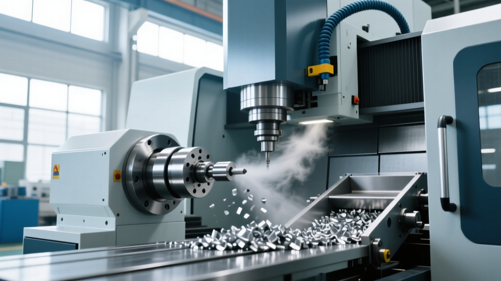
Chip conveyors are the first line of defense in managing bulk material removal. However, poor conveyor maintenance directly impacts CNC machine tooling by altering coolant chemistry. When hinge-belt conveyors run too fast or lack proper wiper tension, they carry excessive coolant out of the sump and into the chip bin. This 'coolant carry-out' forces operators to add straight water to maintain sump levels, diluting the tramp oil inhibitors and biocides.
Research from the National Institute for Occupational Safety and Health (NIOSH) highlights that degraded metalworking fluids due to improper concentration management not only pose respiratory risks to operators but also lose their extreme pressure (EP) lubricity, directly accelerating tool wear and built-up edge (BUE) formation on cutting inserts.
Conveyor Type Maintenance Specifics
Hinge Belt Conveyors: Check chain tension monthly. A loose chain will skip sprocket teeth, causing the belt to jam and trip the overload sensor. Lubricate the drive chain with a high-tack, water-resistant grease to prevent washout from coolant exposure.Scraper / Drag Conveyors: Inspect the UHMW polyethylene wear strips quarterly. Once the scraper flights wear through the poly, they will score the steel trough, creating grooves that trap stringy chips (common in aerospace aluminum and stainless steel machining).The Shift-Based Extraction Maintenance Matrix
To integrate dust and chip management into your existing PM schedule, adopt this tiered maintenance matrix. This framework ensures that extraction systems support, rather than hinder, the longevity of your CNC machine tooling.
Daily Operator Checks (Start of Shift)
- Verify the dust collector magnehelic gauge (differential pressure) is within the green zone (typically 3 to 6 in. w.g. for clean filters).
- Inspect chip conveyor discharge for excessive coolant pooling; adjust belt speed or wiper tension if carry-out exceeds 1 gallon per hour.
- Clear the spindle air-blast nozzle. Ensure the taper-cleaning air blast is free of moisture and delivers at least 40 PSI to blow out particulates before tool clamping.
Weekly Maintenance Technician Tasks
- Empty and clean the primary cyclone or spark-arrestor bin. Accumulated heavy chips here restrict airflow to the main filtration bank.
- Wipe down the machine way covers and inspect the polyurethane wiper seals. If wipers are torn, micron-level dust is being dragged into the linear guideways.
- Test the pulse-jet cleaning cycle manually via the controller override to ensure all solenoid valves actuate audibly.
500-Hour / Bi-Annual Deep Service
- Drop the coolant sump and clean the conveyor trough interior. Remove the fine 'sludge' layer that accumulates beneath the belt, which harbors anaerobic bacteria and degrades coolant pH.
- Inspect the flexible ducting connecting the machine enclosure to the collector. Look for sagging sections where dust can settle and restrict CFM, or micro-tears that leak contaminated air back into the shop.
- Calibrate the coolant refractometer and adjust concentration to the tooling manufacturer's exact specification (usually 8-10% for heavy milling of hardened steels).
Troubleshooting Extraction-Induced Tooling Failures
When CNC machine tooling exhibits premature failure, maintenance teams often blame the tooling vendor or the CAM programming. However, extraction failures are a frequent root cause. Use this diagnostic framework to isolate particulate-induced tooling issues.
| Symptom on Tooling / Workpiece | Probable Extraction Root Cause | Corrective Maintenance Action |
|---|---|---|
| Chatter marks and poor surface finish on finish end mills. | Dust embedded in the spindle taper causing TIR and tool deflection. | Clean spindle taper with a specialized taper wiper and isopropyl alcohol. Check enclosure negative pressure; increase CFM if mist is escaping the doors. |
| Premature flank wear on carbide inserts during dry machining. | Dust collector airflow is insufficient to evacuate abrasive chips from the cut zone, causing recutting. | Inspect flexible ducting for crushing or internal dust dams. Clean pulse-jet valves and check compressed air pressure to restore filter permeability. |
| Corrosion and pitting on unused toolholders stored in the carousel. | Coolant mist is bypassing the extractor and settling inside the tool magazine. | Upgrade to a PTFE membrane mist collector. Ensure the machine enclosure door seals are intact and the exhaust louvers are not blocked. |
Securing the Investment
The precision of CNC machine tooling is entirely dependent on the cleanliness of the mechanical interfaces and the stability of the cutting environment. By elevating dust collection and chip conveyor maintenance from a secondary janitorial task to a primary engineering protocol, manufacturing facilities can drastically reduce tooling spend, eliminate unplanned spindle downtime, and maintain the tight geometric tolerances required in modern aerospace and medical machining. Track your differential pressures, monitor your coolant carry-out, and enforce the shift-based matrix to ensure your extraction infrastructure actively protects your cutting assets.