CNC Machine Tending Robots: Bed Size & Envelope Integration
Match CNC machine tending robots to specific bed sizes and work envelopes. Compare reach, payload, and footprint optimization strategies for 2026.
The Geometry of Automation: Why Envelope Constraints Dictate Robot Selection
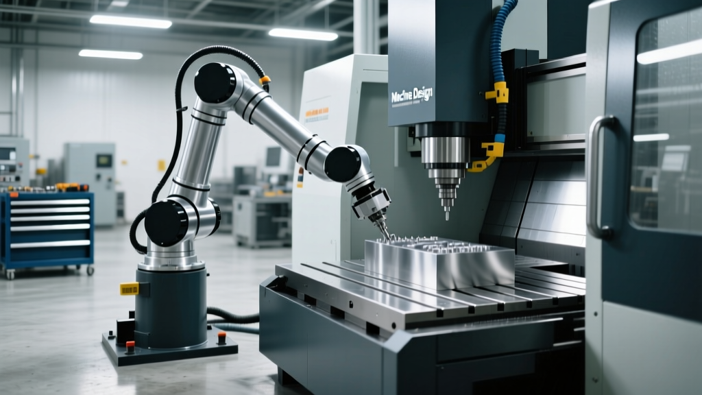
Integrating cnc machine tending robots into a manufacturing cell is rarely a simple plug-and-play operation. The primary engineering bottleneck is not the robot's payload capacity or the CNC's spindle speed; it is the geometric conflict between the machine's physical bed size, its volumetric work envelope, and the robot's kinematic reach. A machine's work envelope is defined by the maximum X, Y, and Z travel of the cutting tool, but for automation purposes, the effective envelope must also account for the operator access zone, door clearance, and the physical space required for the robot's joints to articulate without colliding with the machine's way covers or chip guards.
In 2026, as shops increasingly deploy collaborative and high-payload industrial arms to tend everything from compact vertical machining centers (VMCs) to massive bridge mills, understanding the precise mathematical relationship between CNC bed dimensions and robot reach is critical for avoiding costly integration failures and payload derating.
2026 Market Insight: According to recent integration data, over 35% of failed or delayed CNC tending deployments are caused by 'dead zones'—areas inside the CNC enclosure where the robot's end-of-arm tooling (EOAT) can reach, but the robot's J4 and J5 joints collide with the machine's internal sheet metal guarding.Work Envelope Mapping: 3-Axis VMCs vs. 5-Axis Trunnions
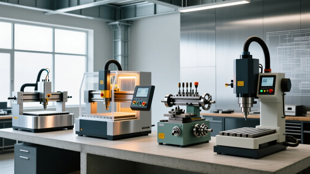
The physical footprint of a CNC machine bed directly dictates the mounting architecture and the required reach of the tending robot. A standard 3-axis VMC like the Haas VF-2SS features a 30" x 20" table with 30" x 20" x 20" travels. Because the table moves along the Y-axis toward the operator, the robot must be positioned to accommodate the table's maximum forward excursion. If the robot is mounted too close to the machine on a standard floor pedestal, the Y-axis travel will cause the machine table to collide with the robot arm during automated loading cycles.
The 5-Axis Z-Axis Clearance Problem
When upgrading to a 5-axis machine like the DMG MORI DMU 50 3rd Gen or a Mazak VARIAXIS i-800 NEO, the bed size is often smaller, but the Z-axis clearance requirement is drastically deeper. The trunnion table rotates the part 120 degrees or more, requiring the tending robot to reach down into a deep enclosure to load the chuck or fixture. A standard 6-axis robot mounted at floor level will experience joint singularity or exceed its Z-reach limit. To resolve this, integrators must utilize custom riser pedestals (typically costing between $2,500 and $5,500) to elevate the robot base, aligning its J1 rotational axis with the centerline of the CNC trunnion.
Robot Reach vs. Payload: The 2026 Tending Matrix
When selecting cnc machine tending robots, manufacturers must evaluate the robot's maximum reach against the CNC's bed width. However, a robot's rated payload is only valid at its center of gravity or a specific reach distance. At maximum extension, the moment of inertia on the J2 and J3 servos spikes, forcing the controller to derate the allowable payload to prevent faulting. The table below maps current leading robot models to ideal CNC bed sizes, accounting for realistic payload derating at maximum reach.
| Robot Model (2026) | Max Reach | Rated / Derated Payload | Ideal CNC Bed Width | Est. System Cost |
|---|---|---|---|---|
| Universal Robots UR20 | 1,750 mm | 20 kg / 14 kg | 20" - 32" VMCs | $65k - $85k |
| FANUC CRX-25iA | 1,889 mm | 30 kg / 22 kg | 30" - 48" VMCs/Lathes | $75k - $98k |
| KUKA KR CYBERTECH nano | 2,011 mm | 10 kg / 8 kg | Large Gantry Mills | $85k - $115k |
Overcoming Deep Envelopes: Linear Tracks and Gantry Systems
For long-bed CNC lathes like the Okuma GENOS L460-MY or extended-bed VMCs exceeding 50 inches in width, a single stationary robot cannot cover the chuck, tailstock, and part catcher without exceeding its kinematic limits. Attempting to mount a massive 2000mm+ reach robot on the floor introduces severe footprint penalties and requires extensive safety caging.
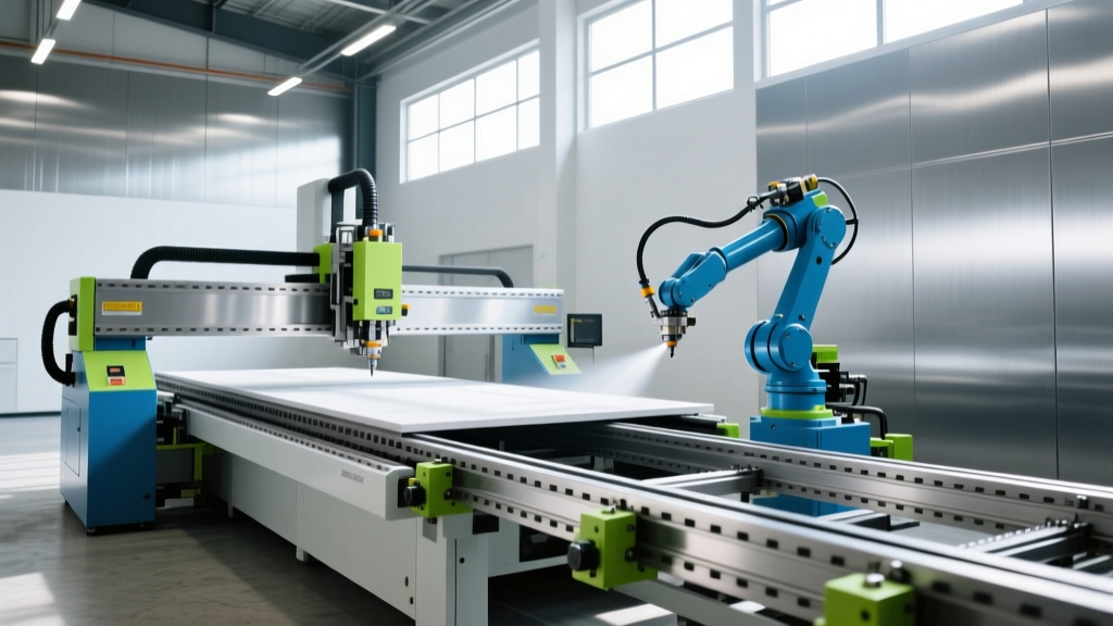
The industry standard solution for large work envelopes in 2026 is the integration of a 7th-axis linear track. Brands like Rollon and Güdel provide precision-ground linear rails that allow a mid-reach robot (like the FANUC CRX-25iA) to traverse laterally alongside the CNC bed. This effectively turns a 1,889mm spherical work envelope into a multi-meter cylindrical envelope. While adding a 7th-axis track increases the total cell cost by $18,000 to $30,000 and requires complex PLC synchronization via PROFINET or EtherNet/IP, it allows the use of a smaller, faster robot while maintaining strict safety clearances.
End-of-Arm Tooling (EOAT) Reach Extensions
Integrators often overlook the fact that the robot's reach is only half of the equation; the EOAT bridges the gap between the robot's wrist and the CNC fixture. By utilizing telescopic grippers or low-profile quick-change tooling systems (such as the Robotiq 2F-140 with custom extension flanges), shops can effectively add 150mm to 250mm of reach. This mechanical extension allows a mid-tier robot to tend a machine bed one size larger than its native specifications would suggest, saving $15,000+ on a robot upgrade. However, every millimeter of EOAT extension increases the torque on the robot's J5 and J6 wrist joints, requiring careful payload recalculation in the robot's native configuration software.
Safety Perimeter Calculations for Tight Envelopes
When matching a robot to a compact CNC bed, the physical footprint of the safety perimeter becomes a limiting factor. According to guidelines published by the Association for Advancing Automation (A3) and the ISO 10218-2 / TS 15066 standards, collaborative and speed-and-separation monitoring (SSM) applications require a calculated minimum safety distance.
"The minimum separation distance (S) is calculated using the formula: S = (V_h × T_r) + (V_h × T_s) + C. Where V_h is the speed of the human operator (typically 1600 mm/s), T_r is the robot response time, T_s is the safety controller response time, and C is the intrusion distance based on the sensor's resolution. In tight CNC cells, if the calculated 'S' exceeds the available floor space between the machine door and the aisleway, hard physical guarding with interlocked gates must replace optical SSM systems."
For small-bed machines like the Haas Mini Mill (16" x 12" bed), floor space is at a premium. Utilizing a mobile cobot cart with a localized safety scanner allows the robot to tend the machine while dynamically reducing its speed to 250 mm/s when an operator enters the narrow envelope, bypassing the need for massive fixed fencing.
Decision Framework: Selecting the Tending Architecture by Bed Size
Use the following framework to specify the correct robot mounting and reach architecture based on your CNC machine's physical bed dimensions:
- Small Bed (Under 24" × 16"): Utilize a collaborative robot (e.g., UR12e or FANUC CRX-10iA/L) mounted on a mobile pneumatic cart. The short reach requirement (under 1300mm) allows the robot to reach the chuck without a riser, minimizing the cell footprint.
- Medium Bed (30" × 18" to 48" × 20"): Deploy a floor-mounted 6-axis robot with a 1700mm+ reach. A 24-inch to 36-inch riser pedestal is mandatory to clear the machine's Y-axis way covers and provide adequate Z-axis clearance for the EOAT to maneuver over vise jaws.
- Large / Long Bed (Over 50" Width or Length): Do not attempt to use a single ultra-long-reach robot. The payload derating and cycle time penalties are too severe. Invest in a 7th-axis linear track to traverse a mid-reach robot, or deploy a dual-robot cell (one for loading raw stock, one for unloading finished parts) positioned on opposite sides of the CNC enclosure.
Final Integration Checklist
Before finalizing a purchase order for any CNC tending system, demand a 3D kinematic simulation (using software like Visual Components or RoboDK) from your integrator. This simulation must map the exact sheet metal guarding of your specific CNC model, the fully extended Y-axis travel, and the maximum Z-height of your tallest vise or tombstone fixture. Only through rigorous volumetric mapping can you ensure the robot will seamlessly navigate the machine's work envelope without catastrophic collisions.