CNC Painting Machine Bed Sizes: 2026 Work Envelope Guide
Compare CNC painting machine bed sizes and work envelopes. Analyze 3-axis gantry vs. 7-axis robotic track systems for 2026 manufacturing layouts.
The definition of a CNC painting machine's work envelope has fundamentally shifted. Historically, buyers evaluated flatbed dimensions (X and Y travel) and Z-axis clearance. In 2026, the rapid adoption of multi-axis articulated robots mounted on linear tracks has replaced simple Cartesian geometry with complex, overlapping cylindrical envelopes. Selecting the correct bed size and kinematic reach is no longer just about fitting the part; it is about managing overspray containment, avoiding robotic singularities, and optimizing facility footprint ratios.
The Kinematic Divide: Gantry Beds vs. Linear-Track Articulated Arms
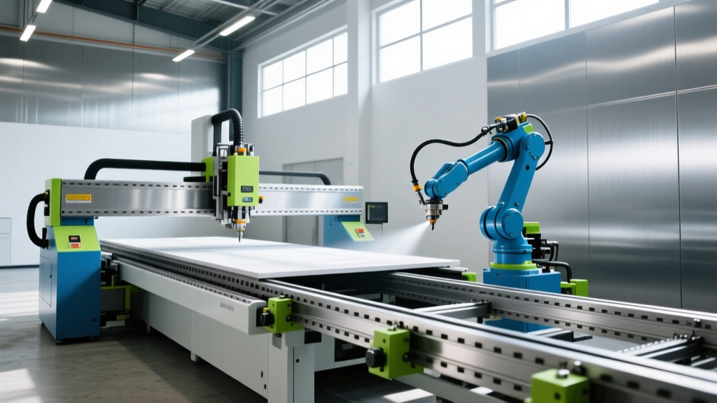
Modern automated finishing systems fall into two primary architectural categories, each dictating a vastly different approach to work envelope calculation. Understanding this divide is critical before allocating floor space or designing downdraft ventilation pits.
Cartesian and Reciprocating Flatbed Systems
Traditional CNC painting machines, such as reciprocating spray booths and 3-axis Cartesian gantries, operate on strict orthogonal planes. The work envelope is a perfect rectangular prism. If a machine specifies a 1300mm x 3000mm bed, the usable painting area is exactly that, minus a 50mm to 100mm margin for gun deceleration at the stroke ends. These systems excel in high-throughput, low-geometry-variance environments like flat-panel furniture manufacturing and modular architectural cladding.
7-Axis Articulated Track Systems
For complex 3D geometries—such as wind turbine nacelles, aerospace fuselages, and heavy earthmoving equipment—manufacturers now deploy 6-axis articulated robots mounted on a 7th-axis linear floor track. The work envelope here is not a rectangle, but a moving series of overlapping spheres. According to data from the Association for Advancing Automation (A3), 7-axis painting cells now account for over 40% of new heavy-industry finishing installations due to their ability to wrap around complex contours without repositioning the workpiece.
Work Envelope Matrix: System Comparison
The table below benchmarks the three dominant CNC painting machine configurations currently deployed in industrial settings, highlighting the critical differences between physical footprint and effective work envelope.
| System Type | Kinematic Axes | Standard Max Envelope (X/Y/Z) | Footprint-to-Envelope Ratio | 2026 Avg. Price Range |
|---|---|---|---|---|
| Reciprocating Flatbed (e.g., Cefla CFC) | 3 to 4 | 1500mm / 3500mm / 400mm | 1.4 : 1 | $180,000 - $350,000 |
| Cartesian Gantry (e.g., Superfici Vertex) | 3 to 5 | 3000mm / 6000mm / 1200mm | 1.8 : 1 | $450,000 - $850,000 |
| 7-Axis Linear Track (e.g., CMA GR6 Series) | 7 | 40,000mm / 6000mm / 4500mm | 3.5 : 1 | $950,000 - $2.2M+ |
Navigating the 'Dead Zone' in Robotic Envelopes
When evaluating CMA Robotics or similar articulated CNC painting machines, buyers frequently make a critical error: confusing the robot's maximum reach radius with its effective painting envelope. A 6-axis robot with a 3,200mm reach does not provide a usable 3,200mm painting radius.
Engineering Warning: The Base Singularity ProblemArticulated robots suffer from 'dead zones' directly above and immediately adjacent to their base pedestal (Axis 1). In these zones, the robot must perform rapid, multi-axis simultaneous rotations to maintain gun orientation, leading to singularities, uneven paint deposition, and excessive wear on the wrist actuators. Always subtract a minimum 800mm cylindrical radius around the robot base from your calculated work envelope when designing part placement on the turntable.
Overspray Containment vs. Kinematic Reach
The physical walls of the spray booth further compress the work envelope. High-velocity downdraft booths require a minimum 600mm to 900mm clearance between the extreme extension of the spray gun and the booth walls or water-wash filters to prevent turbulent air currents from disrupting the atomization fan pattern. Therefore, a robot with a 3-meter kinematic reach installed in a 5-meter wide booth effectively yields only a 3.2-meter wide usable painting envelope.
Industry-Specific Bed Sizes and Envelope Benchmarks
Work envelope requirements are strictly dictated by the geometry and production volume of the target industry. Below are the precise specifications driving 2026 capital equipment purchases across three major sectors.
1. Aerospace and Wind Energy (Large-Format Articulated)
Painting a 60-meter wind turbine blade or a commercial aircraft fuselage requires massive linear travel. Manufacturers utilize dual-robot setups on synchronized 7th-axis tracks.
- Typical Linear Track Length: 20,000mm to 45,000mm.
- Z-Axis Clearance: Up to 8,000mm, often requiring the robot to be mounted on a vertical elevating column (adding an 8th axis) to reach the top of a fuselage without stretching into a singularity.
- Capital Cost: $1.8M to $3.5M for fully enclosed, climate-controlled, multi-robot hangar systems.
2. Woodworking and Flat-Panel Furniture (Reciprocating Flatbed)
For MDF doors, cabinet fronts, and flat architectural panels, articulated arms are overkill and too slow. CNC reciprocating painting machines utilize oscillating carriages that traverse a fixed-width bed.
- Standard Bed Widths: 1300mm (standard European panel) and 2100mm (oversized doors).
- Feed Speeds: 3 to 7 meters per minute, vastly outpacing robotic cells.
- Key Provider Benchmark: Systems like those detailed by Cefla Finishing integrate UV-curing ovens directly inline, meaning the total machine footprint extends to 12,000mm in length, though the active spray envelope remains under 4,000mm.
3. Heavy Machinery and Agriculture (Turntable Gantry)
Tractors, excavators, and combine harvesters are painted using a hybrid approach: a 3-axis Cartesian gantry combined with a heavy-duty rotary positioner (turntable).
- Turntable Diameter: 3,500mm to 5,000mm, supporting up to 20,000 kg.
- Gantry Z-Axis Drop: 2,500mm to reach into deep chassis cavities and undercarriages.
- Advantage: The rotary table effectively multiplies the X/Y envelope of the gantry by allowing the part to be spun into the optimal spray angle, reducing the required gantry travel and minimizing booth width.
The 2026 Facility Sizing Decision Framework
Do not size your facility based on the machine's kinematic limits. Use this sequential framework to determine the actual floor space and work envelope required for your CNC painting machine installation.
- Define the Bounding Box: Measure the absolute maximum X, Y, and Z dimensions of your largest target part. Add 15% to the Z-axis to account for lifting fixture clearance.
- Calculate Gun-to-Part Standoff: Add the required spray gun distance (typically 250mm to 350mm for HVLP, 400mm for airless) to all sides of the bounding box.
- Apply the Airflow Buffer: Add 900mm to the X and Y axes to ensure laminar downdraft airflow is not disrupted by the part or the robot arm, which causes dry spray and orange-peel defects.
- Determine Robot Mounting: If the buffered envelope exceeds 2,500mm in any single direction, abandon fixed-base 6-axis robots. Specify a 7-axis linear track or a Cartesian gantry to maintain consistent gun velocity and orthogonal spray angles.
- Factor in Maintenance Access: Add a mandatory 1,200mm walkway on the non-operating side of the machine bed for technicians to access fluid regulators, pump manifolds, and track lubrication points without entering the active spray zone.
By treating the work envelope as a dynamic intersection of kinematics, fluid dynamics, and facility architecture, manufacturers can eliminate the costly bottlenecks of overspray turbulence and robotic singularity delays that plague poorly planned finishing cells.