CNC Machine 3D Printing Controllers: Operator Training Guide
Master hybrid CNC machine 3D printing controllers. Compare Siemens, Fanuc, and LinuxCNC interfaces, G-code mapping, and operator training protocols.
The Paradigm Shift: Subtractive Logic Meets Additive Deposition
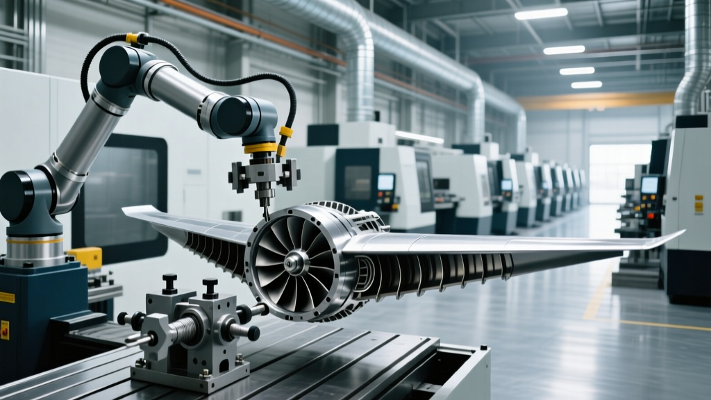
Operating a hybrid manufacturing system requires a fundamental rewiring of traditional machining instincts. When transitioning to cnc machine 3d printing workflows—whether via Directed Energy Deposition (DED), Wire Arc Additive Manufacturing (WAAM), or retrofitted fused filament extrusion—the controller interface ceases to be just a material removal dashboard. It becomes a thermal and fluid dynamics management hub. Operators trained in rigid tapping, constant surface speed, and chip evacuation must now master variable flow rates, interpass temperature thresholds, and shielding gas flow dynamics.
Core Operational Difference: In subtractive CNC, the controller manages cutting forces and tool deflection. In hybrid CNC additive manufacturing, the controller manages thermal mass accumulation and deposition kinematics. A 2mm dwell time error in milling leaves a minor chatter mark; in 3D printing, it causes localized overheating, grain structure degradation, and catastrophic layer delamination.Dominant Controller Platforms in Hybrid Manufacturing
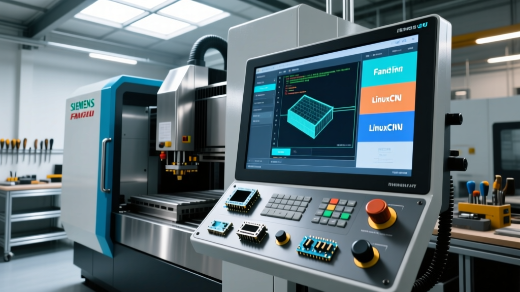
The industrial landscape for hybrid CNC additive systems is dominated by three distinct controller architectures, each requiring specific operator training pathways.
1. Siemens Sinumerik ONE (Additive Manufacturing Option)
Siemens dominates the high-end hybrid market, notably powering systems like the DMG MORI LASERTEC series. The Sinumerik ONE platform utilizes a dedicated 'Additive Manufacturing' technology cycle. Operators must learn to navigate the AM HMI, which overlays thermal imaging data and powder nozzle collision monitoring directly onto the standard toolpath view.
- Licensing & Cost: The additive option package typically adds $9,500 to $12,000 to the base controller cost.
- Key Feature:
COMPCAD(Compression) is critical. It converts thousands of tiny linear G-code segments from the slicer into smooth NURBS splines, preventing the look-ahead buffer from starving and causing dwell marks on the deposited bead.
2. Fanuc 31i-B5 with 5-Axis Additive Cycles
For multi-axis WAAM and DED systems (such as those integrated into Mazak INTEGREX platforms), Fanuc's 31i-B5 provides the simultaneous 5-axis interpolation required to deposit material on complex, non-planar surfaces. Operators must master G05.1 Q1 (Smooth Tolerance Control) to maintain consistent bead width during rapid directional changes.
3. Open-Source Retrofits: LinuxCNC & Mach4
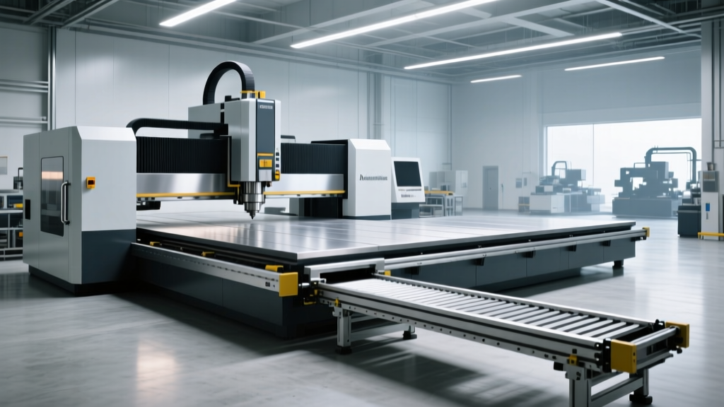
For job shops retrofitting 3-axis CNC routers (like Tormach or Shapeoko industrial models) with E3D or Bondtech extruders for high-temp polymer 3D printing, LinuxCNC is the standard. Training here focuses on hardware abstraction. Operators must map the spindle PWM output to the extruder heater block and configure Mesa Electronics 7i76E boards (approx. $249) to handle the 10V analog signals required for precise flow-rate control.
Parameter Mapping: G-Code Translation for Deposition
The steepest learning curve for veteran machinists is re-reading G-code through an additive lens. Below is the critical translation matrix operators must memorize for hybrid DED systems.
| Traditional Milling Code | Hybrid Additive Function | Operational Impact & Training Focus |
|---|---|---|
S (Spindle Speed RPM) |
Laser Power (W) / Wire Feed (mm/min) | Dictates energy density. Operators must monitor for keyholing (too high) or lack of fusion (too low). |
M8 (Coolant On) |
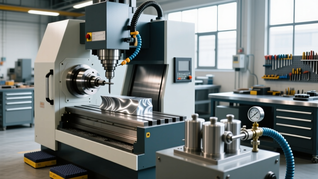
Argon/Nitrogen Shielding Gas On | Prevents oxidation in the melt pool. Flow rate (CFH) must be verified via physical rotameter before cycle start. |
F (Feedrate) |
Deposition Travel Speed | Directly controls bead width and layer height. Must remain perfectly synchronized with S (wire feed). |
M3 (Spindle CW) |
Laser Emission / Arc Strike | Safety critical. Interlocks must be verified to ensure enclosure doors are sealed against UV/radiation. |
Critical Operator Training Protocols
According to research published by NIST on Additive Manufacturing, the primary failure mode in hybrid systems is not software slicing errors, but physical setup and calibration drift. Training protocols must prioritize the following physical-to-digital handoffs.
Step 1: Dual Tool Center Point (TCP) Calibration
Hybrid machines utilize a milling spindle and a deposition head (often mounted on an HSK63 taper or a dedicated secondary gantry). Operators must perform a dual TCP calibration. Using a laser tracker or a Renishaw OMP60 probe, the offset between the milling tool tip and the powder nozzle focal point must be mapped to within 0.05mm. If this offset drifts due to thermal expansion in the Z-axis ballscrew, the subsequent milling pass will gouge the freshly printed near-net-shape part.
Warning: Never rely solely on CAD nominal offsets for the deposition head. The focal point of a DED laser shifts based on the powder mass flow rate. Operators must print a single-layer calibration grid and measure the bead width with digital calipers to dynamically update the TCP offset in the controller's tool table.Step 2: Interpass Temperature Management
Unlike subtractive cycles where the operator can pause indefinitely, CNC machine 3D printing requires strict thermal pacing. Advanced controllers like the Siemens Sinumerik allow operators to program WAITM (Wait for Temperature) commands. The operator must train on integrating IR pyrometer feedback loops into the PLC, ensuring the controller halts the next deposition layer until the base metal drops below the critical interpass temperature (e.g., 250°C for 316L stainless steel).
Step 3: Post-Processor Verification
Operators must understand how CAM software (like Autodesk PowerMill or hyperMILL) generates hybrid toolpaths. A common error occurs when the post-processor outputs standard G00 (Rapid Traverse) between deposition points. In additive manufacturing, rapid moves with the laser active will scar the part. Operators must audit the first 50 lines of code to ensure G01 (Linear Interpolation) is used for all approach and retract vectors, with the laser state (M3/M5) strictly toggled during safe Z-height moves.
Troubleshooting Interface Lag and Thermal Drift
When operating retrofitted CNC machines for large-format polymer 3D printing, operators frequently encounter 'blobbing' at the start and end of toolpaths. This is rarely a slicer error; it is a controller communication latency issue.
- Symptom: Excess material extruded at sharp corners.
- Root Cause: The controller's look-ahead buffer calculates the deceleration for the corner, but the PWM signal to the extruder motor has a 40-millisecond lag, continuing to push filament while the physical axis slows down.
- Operator Fix: In LinuxCNC, adjust the
EXTRUDE_FACTORscaling or implement 'pressure advance' (linear advance) algorithms that preemptively retract the filament 2mm before the axis reaches the deceleration point. In Mach4, utilize the 'Threading' wizard to map the extruder as a synchronous slave axis to the X/Y movement, eliminating PWM lag entirely.
Industry Standards and Safety Interlocks
As hybrid systems become more prevalent, DMG MORI's integration of CE-compliant enclosures highlights the necessity of advanced safety training. Operators must be trained to test the optical density (OD) ratings of the machine's viewing windows. For DED systems utilizing 1070nm diode lasers, standard polycarbonate shields are transparent to the laser wavelength and offer zero retinal protection. Controllers must be hardwired to safety relays that instantly kill the M3 laser emission circuit if the enclosure door limit switch is breached, bypassing the software PLC entirely.
Furthermore, when evaluating aftermarket hybrid deposition heads like those developed by Hybrid Manufacturing Technologies (AMBIT systems), operators must undergo specific training on the proprietary M-code dictionaries these toolheads inject into standard Fanuc and Siemens environments. Mastery of these hybrid interfaces transforms the CNC operator from a simple button-pusher into a true metallurgical process engineer, capable of holding tolerances of ±0.005 inches on as-printed and finish-milled aerospace components.