Fixturing a 6 Axis CNC Machine for Complex Aerospace Parts
Advanced workholding and fixturing methods for 6 axis CNC machines, featuring aerospace and medical case studies, specific clamp models, and real failure modes.
The Physics of 6-Axis Fixturing: Rigidity vs. Tool Clearance
Securing a workpiece for simultaneous multi-axis interpolation requires overcoming extreme radial cutting forces while maintaining unobstructed toolpath clearance. When operating a 6 axis CNC machine—typically configured as a 5-axis trunnion mill integrated with a 6th-axis robotic part positioner, or a 6-axis articulated robotic milling cell—the workholding system must accommodate complex spatial rotations without colliding with the spindle head or tool holder.
Standard vise setups fail in these environments. The primary engineering conflict is the inverse relationship between clamping surface area (which provides rigidity) and tool access (which requires minimal fixture footprint). According to research from NIST Advanced Manufacturing, fixture deflection accounts for up to 40% of dimensional errors in multi-axis aerospace milling. To achieve tolerances below 0.015 mm on complex contours, manufacturers must deploy specialized workholding that anchors the part from the underside or utilizes conformal clamping.
Critical Warning: Harmonic ResonanceIn 6-axis robotic milling cells, the fixture and part act as a combined mass-spring system. If the clamping frequency matches the spindle's tooth-pass frequency (often between 800 Hz and 1,200 Hz during high-speed finishing), harmonic resonance will cause severe chatter, destroying surface finish and tool life. Always perform a tap-test on the fixtured part to identify natural frequencies before finalizing CAM feed rates.
Case Study 1: Aerospace Impeller Milling on a 6-Axis Robotic Cell
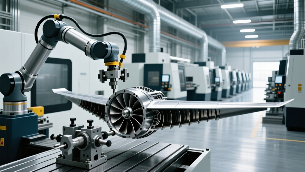
Machining a Ti-6Al-4V titanium impeller requires deep tool reach into narrow blade channels. A tier-1 aerospace supplier utilized a 6-axis robotic milling cell (a KUKA KR Quantec arm equipped with a 12,000 RPM HSK-A63 spindle) to rough and finish the impeller. The initial setup used standard mechanical toe-clamps, which required multiple step-downs and re-fixturing to avoid tool collisions, resulting in a 42-minute roughing cycle.
The Fixturing Intervention
The engineering team replaced the mechanical clamps with a hybrid workholding system:
- Base Fixation: A custom porous aluminum vacuum chuck integrated with a Schunk Vero-S NSE plus 138 zero-point clamping system. The Schunk pallet provides a pull-in force of 1,500 N and a static holding force of 6,000 N, anchoring the fixture to the robotic cell's rotary table with less than 0.005 mm repeatability.
- Top Clamping: Low-profile hydraulic swing clamps with custom 3D-printed titanium conformal clamp heads that matched the impeller's outer shroud contour.
Results and Metrics
By securing the part entirely from the outer shroud and utilizing the vacuum base, the toolpath was freed from internal obstructions. The roughing cycle time dropped from 42 minutes to 28 minutes (a 33% improvement), and the scrap rate due to clamp-induced vibration dropped to zero. The total investment for the custom hydraulic fixture and Schunk zero-point pallet was $18,400, yielding an ROI in under three months based on a 500-part annual production run.
Case Study 2: Medical Orthopedic Implants (Cobalt Chrome)
Femoral knee components machined from Cobalt Chrome (CoCr) present a different 6-axis challenge. These parts feature highly polished, complex organic surfaces that cannot be marred by clamp marks. A medical device manufacturer running a DMG MORI DMU 50 3rd Generation (configured with a 6-axis robotic automation cell for part flipping) struggled with a 12% scrap rate caused by cosmetic marring and micro-movement during the final 5-axis simultaneous finishing pass.
Conformal PEEK Soft Jaws and Pitbull Clamps
The solution required abandoning standard aluminum soft jaws. The team engineered custom soft jaws machined from PEEK (Polyether ether ketone), a high-performance thermoplastic with a Shore hardness of 85D. PEEK is rigid enough to resist the 1,200 N radial cutting forces of CoCr finishing passes, yet soft enough to prevent marring the polished implant surface.
To secure the PEEK jaws, they utilized Mitee-Bite Pitbull clamps. The Pitbull design bites into the raw material stock with a clamping force up to 18,000 lbs, requiring only 0.125 inches of clearance. This ultra-low profile allowed the 6-axis robotic arm to reposition the part for secondary operations without the spindle colliding with the workholding hardware.
'The transition to PEEK conformal jaws combined with ultra-low-profile clamps reduced our cosmetic scrap rate on CoCr femoral components from 12% to 1.4%, saving approximately $115,000 annually in wasted material and machine time.' — Lead Manufacturing Engineer, Orthopedic Division.
Comparative Matrix: Workholding Solutions for 6-Axis Kinematics
Selecting the correct workholding for a 6 axis CNC machine depends heavily on the part geometry, material, and production volume. The matrix below compares the four dominant fixturing methods used in multi-axis environments.
| Method | Max Holding Force | Tool Access | Best Application | Approx. Cost |
|---|---|---|---|---|
| Zero-Point Vacuum | ~4,000 N (Shear) | Excellent (5 sides open) | Thin-walled aerospace skins | $8,000 - $15,000 |
| Hydraulic Toe-Clamps | ~25,000 N | Moderate (Requires top clearance) | Heavy roughing, titanium blocks | $3,500 - $7,000 |
| Magnetic Chucks (EP) | ~12,000 N/cm² | Excellent (5 sides open) | Ferrous die/mold roughing | $4,000 - $9,000 |
| Mechanical Pitbull | ~80,000 N | High (Ultra-low profile) | Medical implants, 6-axis flipping | $400 - $800 per unit |
Advanced Fixturing: Trunnion Integration and Thermal Management
When mounting fixtures to the B or C axis trunnion of a 6 axis CNC machine, gravity vectors shift continuously. A fixture that relies on friction alone will fail when the trunnion rotates to 90 degrees, subjecting the part to pure shear forces. Zero-point clamping systems are mandatory in these orientations. The Schunk Vero-S system utilizes a patented clamping pin mechanism that mechanically locks the pallet, ensuring zero movement even when subjected to 2G centrifugal forces during rapid rotary indexing.
Thermal Displacement Mismatch
A frequently overlooked failure mode in multi-axis machining is thermal expansion mismatch between the fixture and the workpiece. If a titanium part (Coefficient of Thermal Expansion: 8.6 µm/m·°C) is fixtured in an aluminum tombstone (CTE: 23.6 µm/m·°C), the fixture will expand nearly three times faster than the part as the cutting zone heats up. In a 400mm long aerospace structural component, a 15°C temperature rise in the fixture results in a 0.14 mm differential expansion—enough to cause the part to bow, bind, or spring out of the clamps upon release.
The Fix: Use steel or ductile iron tombstones and fixture bases when machining titanium or Inconel. While heavier and harder to machine, their CTE (approx. 11-12 µm/m·°C) closely matches high-temperature aerospace alloys, neutralizing thermal displacement errors during long 6-axis cycle times.
Failure Modes in Multi-Axis Fixturing (And How to Avoid Them)
Even with premium workholding, 6-axis kinematics introduce unique edge cases. Recognize and mitigate these common failure modes:
- Coolant Washout in Vacuum Chucks: High-pressure through-spindle coolant (up to 1,000 PSI) can breach the O-ring seals of a vacuum chuck, breaking the vacuum seal mid-cycle. Solution: Route high-pressure coolant lines externally and use mechanical clamps for operations exceeding 300 PSI.
- Robotic Arm Deflection: In 6-axis robotic milling, the cutting forces push back against the robot arm, not just the fixture. If the fixture is infinitely rigid but the robot arm deflects by 0.2 mm, the part is still out of tolerance. Solution: Implement closed-loop force sensing or use the 6-axis robot strictly for part positioning (mill-turn style) while a rigid 5-axis spindle performs the cutting.
- Chip Nesting in Zero-Point Systems: Fine titanium or CoCr chips can lodge in the zero-point clamping chuck, preventing the pallet from seating fully and causing a Z-axis offset error. Solution: Integrate automated air-blast cleaning cycles into the CNC macro program immediately before the pallet locks into position.