CNC ID Grinding Machine Spindle Speed & Feed Rate Optimization
Master CNC ID grinding machine spindle speed and feed rate optimization. Learn technical specs, SFM calculations, and troubleshooting for bore finishing.
The Physics of Internal Grinding: Kinematic Constraints
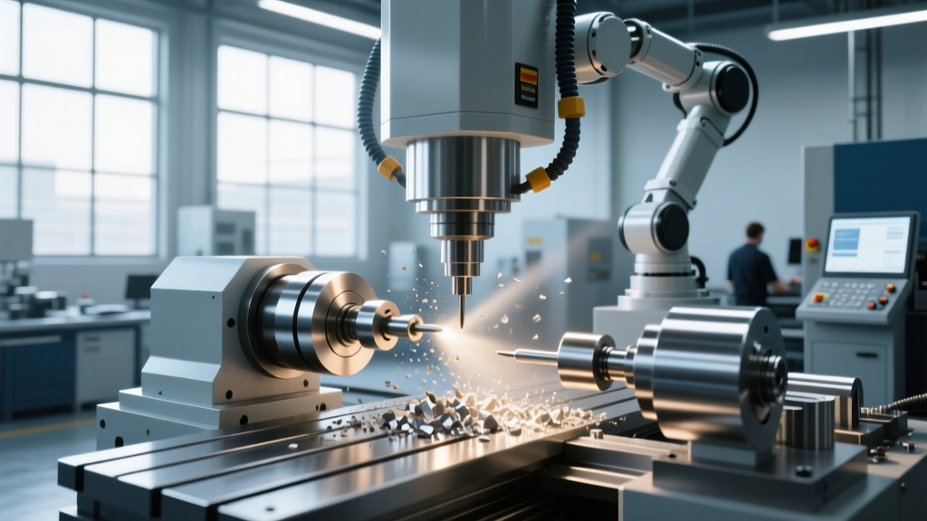
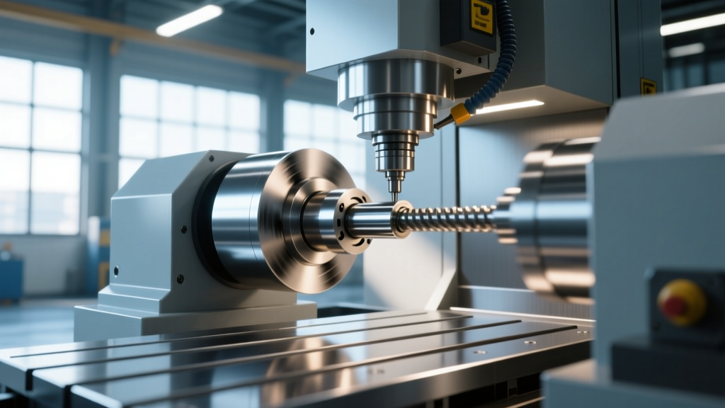
Internal cylindrical grinding presents a unique set of kinematic and mechanical challenges compared to external (OD) grinding. When programming a CNC ID grinding machine, the primary constraint is the bore envelope itself. The grinding wheel must fit inside the workpiece, which severely limits the wheel diameter and, consequently, the stiffness of the entire grinding system. Because the wheel spindle is cantilevered into the bore, it acts as a lever, making it highly susceptible to deflection, chatter, and taper generation.
Optimizing spindle speed and feed rate on modern CNC ID grinders—such as those equipped with Siemens Sinumerik ONE or Fanuc 31i-B5 controls—requires moving beyond generic surface speed charts. It demands a precise understanding of the wheel-to-bore diameter ratio, high-frequency spindle dynamics, and the elastic recovery of the machine-workpiece system during spark-out passes.
The Geometric Rule: Wheel-to-Bore Diameter Ratio
Before calculating RPM or feed rates, you must establish the correct grinding wheel diameter ($D_w$) relative to the bore diameter ($D_b$). The industry-standard technical specification dictates that the wheel diameter should be 60% to 80% of the bore diameter.
- If $D_w$ < 60% of $D_b$: The wheel spindle overhang is excessive relative to the wheel mass. This causes severe harmonic chatter, rapid wheel breakdown, and a pronounced taper at the bottom of blind bores.
- If $D_w$ > 80% of $D_b$: The clearance between the wheel and the bore wall is too tight. This restricts coolant flow, prevents the efficient evacuation of swarf, and causes thermal damage (burn) to the workpiece surface.
For blind bores, you must also account for the run-out distance. The wheel must be able to traverse past the grinding zone to allow for the spark-out passes without the spindle housing colliding with the workpiece face. This often forces the use of a slightly smaller wheel (closer to the 60% threshold) and necessitates a stiffer, shorter spindle nose.
Calculating Optimal Spindle Speed (RPM) for ID Grinding
Surface speed (SFM or m/s) is the critical metric for abrasive performance. However, because the ID grinding wheel diameter is small, achieving the required surface speed demands exceptionally high spindle RPM. The formula to calculate the required wheel spindle speed ($N_w$) is:
$N_w = \frac{SFM \times 3.82}{D_w \text{ (in inches)}}$ or $N_w = \frac{V_s \times 1000 \times 60}{\pi \times D_w \text{ (in mm)}}$
Target Surface Speeds by Abrasive Type
According to Norton Abrasives grinding fundamentals, the optimal surface speed varies drastically based on the abrasive grain and bond type. Running a vitrified CBN wheel at the speed of a standard aluminum oxide wheel will glaze the wheel and burn the part.
| Abrasive Type | Bond Type | Target Surface Speed (SFM) | Target Surface Speed (m/s) | Required RPM for 1" (25mm) Wheel |
|---|---|---|---|---|
| Aluminum Oxide (AlOx) | Vitrified | 4,500 - 6,500 | 23 - 33 | 17,190 - 24,830 |
| Silicon Carbide (SiC) | Vitrified | 5,000 - 6,500 | 25 - 33 | 19,100 - 24,830 |
| Cubic Boron Nitride (CBN) | Vitrified / Metal | 8,000 - 12,000 | 40 - 60 | 30,560 - 45,840 |
| Diamond | Resin / Metal | 5,500 - 8,000 | 28 - 40 | 21,010 - 30,560 |
As the table demonstrates, grinding a 1-inch bore with a 0.8-inch CBN wheel at 10,000 SFM requires the spindle to rotate at over 47,000 RPM. Standard belt-driven spindles cannot achieve this. Modern CNC ID grinding machines utilize high-frequency motor spindles (often liquid-cooled) capable of sustaining 60,000 to 120,000 RPM with a radial runout of less than 1.0 µm (0.00004") at the flange.
Feed Rate Mechanics: Traverse, Plunge, and Spark-Out
Feed rate optimization in ID grinding is a balancing act between cycle time, surface finish ($R_a$), and geometric accuracy (roundness and cylindricity). The feed parameters are divided into three distinct phases.
1. Traverse (Longitudinal) Feed Rate ($f_a$)
The traverse rate dictates how fast the wheel moves axially through the bore. The golden rule for ID grinding is to set the traverse feed to 1/3 to 1/2 of the wheel width per workpiece revolution.
- Roughing: 0.5 to 0.8 × wheel width (prioritizes material removal rate).
- Finishing: 0.2 to 0.3 × wheel width (ensures overlapping grinding paths for low $R_a$ surface finish).
Note: The workpiece rotational speed ($N_w$) must be synchronized with the traverse rate. Workpiece surface speed should generally be maintained between 50 and 100 SFM (15 to 30 m/min). If the bore diameter is large, the workpiece RPM will be very low, which may require a slower traverse rate to maintain the correct feed-per-revolution ratio.
2. Plunge (Infeed) Rate
Because of the cantilever effect, the ID grinding spindle lacks the rigidity of an OD setup. Aggressive plunge rates will cause the spindle to deflect away from the cut, resulting in a tapered bore (larger at the entrance, smaller at the depth).
- Roughing Infeed: 0.0005" to 0.0015" (0.012mm to 0.038mm) per pass.
- Finishing Infeed: 0.0001" to 0.0003" (0.002mm to 0.008mm) per pass.
3. The Physics of Spark-Out Passes
Spark-out (zero-infeed) passes are non-negotiable in precision ID grinding. When the wheel plunges into the bore, the grinding forces push the spindle back elastically. The actual depth of cut is always less than the programmed CNC infeed. By programming 2 to 4 spark-out passes at the final Z-depth, you allow the spindle and workpiece to "spring back" and remove the remaining material stock. Omitting spark-out passes is the leading cause of out-of-roundness and size variation in bore finishing.
Warning: The High-Speed Air Barrier (Windmill Effect)At 40,000+ RPM, an ID grinding wheel creates a localized high-pressure air barrier that deflects standard low-pressure flood coolant. If coolant does not penetrate the grinding zone, you will experience severe thermal burn and rapid wheel loading. To counter this, modern CNC ID grinders utilize high-pressure through-spindle coolant (1,000+ PSI) or specialized shoe nozzles that match the curvature of the bore to force fluid directly into the cutting arc. For deep-hole ID grinding, consider using a porous grinding wheel that allows coolant to weep through the wheel body itself.
Troubleshooting Feed and Speed Defects in Bore Finishing
When bore tolerances fall outside the acceptable $\pm$0.0002" (5 µm) range, the defect pattern usually points directly to a specific speed, feed, or setup error. Use the following diagnostic matrix to adjust your CNC program.
| Defect Symptom | Probable Root Cause | CNC Program / Setup Correction |
|---|---|---|
| Regenerative Chatter (Spiral or multi-lobed pattern on bore wall) | Wheel speed and workpiece speed are harmonically synchronized; wheel is too hard. | Alter workpiece RPM by 15-20%. Switch to a softer grade wheel or reduce traverse feed rate. |
| Thermal Burn (Discoloration, micro-cracking, tensile residual stress) | Coolant starvation due to air barrier; wheel is loaded/glazed; infeed too aggressive. | Increase coolant pressure; add a dressing cycle; reduce finishing infeed to <0.0002". |
| Bore Taper (Larger diameter at entrance, smaller at depth) | Spindle deflection during traverse; lack of spark-out passes; wheel overhang too long. | Add 2-3 spark-out passes; reduce roughing infeed rate; minimize Z-axis overhang. |
| Bell-Mouthing (Oversize at both ends of a through-bore) | Dwell time at the reversal points of the traverse axis is too long. | Program a slight Z-axis over-travel past the bore edges to ensure uniform dwell time across the entire grinding path. |
Modern Machine Specifications for ID Grinding Success
Achieving sub-micron bore tolerances requires more than just optimal G-code; it requires a machine architecture built for internal kinematics. When evaluating or operating a CNC ID grinding machine, verify the following technical specifications:
- Spindle Runout: Must be < 1.0 µm TIR (Total Indicator Runout) at the mounting flange. High-frequency spindles utilizing hybrid ceramic ball bearings or hydrostatic bearings are mandatory for CBN applications.
- Thermal Stability: The spindle housing and machine bed must feature active thermal compensation or liquid cooling loops. A 2°C shift in ambient shop temperature can alter bore diameter by up to 4 µm in high-precision aerospace alloys.
- Dressing Capabilities: For vitrified CBN and AlOx wheels, the machine must feature an integrated rotary diamond dresser capable of profiling the wheel at precise intervals to maintain the micro-topography required for aggressive stock removal without burn.
For advanced insights into machine stiffness and grinding kinematics, the Studer cylindrical grinding technology resources provide extensive documentation on how hydrostatic guideways and spindle dynamics influence internal bore geometries. Furthermore, continuous monitoring of spindle load via the CNC control's adaptive control algorithms can automatically adjust the infeed rate in real-time, compensating for variations in material hardness and preventing wheel overload.
Mastering CNC ID grinding machine optimization requires treating the spindle speed, feed rate, and coolant delivery as a single, interdependent system. By respecting the geometric constraints of the bore, calculating exact RPM requirements for modern superabrasives, and leveraging spark-out physics to defeat spindle deflection, manufacturers can consistently hold sub-micron tolerances in high-volume production environments.