What Direction Is the Z Axis on the CNC Machine? Portable Field Safety
Discover what direction is the Z axis on the CNC machine during portable field setups. Master safety compliance, gravity risks, and ANSI standards.
The Cartesian Standard vs. Field Reality
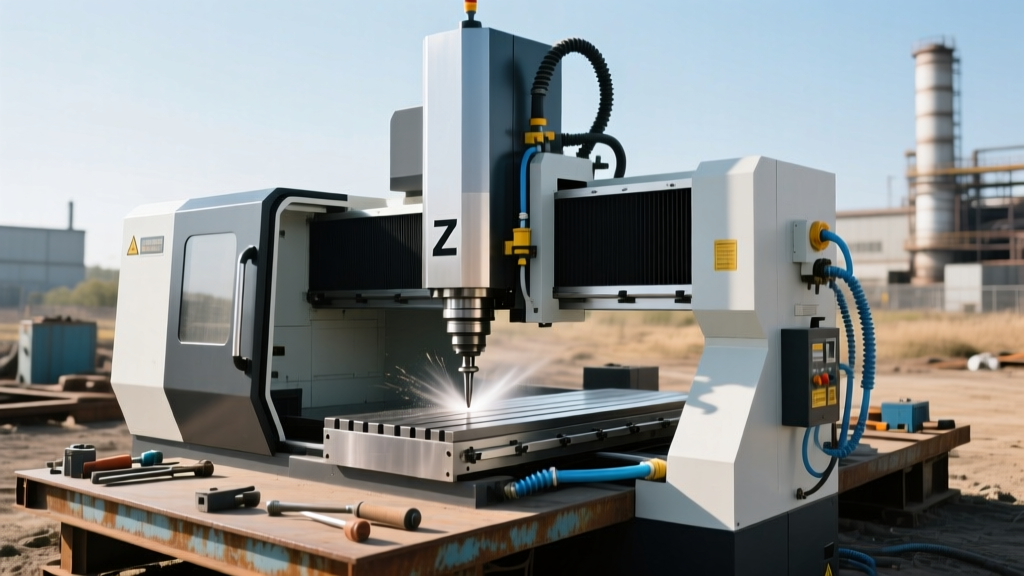
When safety auditors and field technicians ask what direction is the z axis on the cnc machine, the textbook answer relies on the standard right-hand Cartesian coordinate system: the Z-axis is perpendicular to the X-Y plane, typically pointing upward toward the spindle or tool holder. In a traditional machine shop, this means the Z-axis directly opposes gravity. However, in portable field machining—where equipment like the Climax BMX3000 CNC Portable Milling Machine or Mirage CNC Flange Facers are bolted to vertical wind turbine towers, ship hulls, or inverted pipeline flanges—the relationship between the local Z-axis and gravity changes drastically.
Understanding what direction is the z axis on the cnc machine in a non-horizontal setup is not merely an academic exercise; it is a critical compliance and safety variable. The machine's local Z-axis still commands tool depth relative to the workpiece surface, but gravity may now be pulling laterally on the spindle carriage or axially downward on the tool retention system. Failure to account for this spatial shift is a primary cause of tool pullout, axis drift, and catastrophic workpiece damage in field environments.
⚠️ CRITICAL SAFETY WARNING: Never use standard ER collet chucks for portable CNC operations where the local Z-axis is inverted (spindle pointing down) or horizontal. Gravity will overcome the collet's clamping force during high-vibration heavy milling, leading to catastrophic tool drop. Always use Weldon flat (set-screw) or hydraulic toolholders for non-vertical Z-axis field setups.Safety Standards & Compliance Framework
Field machining operates under strict regulatory scrutiny due to the uncontrolled nature of remote environments. Compliance with both OSHA regulations and international machine safety standards requires explicit documentation of how gravitational vectors affect machine axes.
- OSHA 1910.212 (General Requirements for All Machines): Mandates that machine guarding and tool retention must account for all operational orientations. OSHA 1910.212 requires that portable machinery anchored in non-standard positions utilize secondary retention systems to prevent component detachment due to gravity or vibration.
- ISO 16090-1 (Machine Tools Safety - Milling Machines): Specifies safety requirements for milling operations, including portable setups. ISO 16090-1:2017 outlines that when the Z-axis operates parallel to the ground (horizontal spindle) or inverted, the machine must feature self-locking leadscrews or electromagnetic Z-axis brakes to prevent carriage drop during power loss.
- ANSI B11.8 (Safety Requirements for Manual Turning, Boring, Drilling, and Milling): Requires that workholding and machine anchoring in field environments be engineered to withstand dynamic cutting forces combined with the static load of the machine's own weight on non-horizontal planes.
Gravity Impact Matrix: Z-Axis Orientation & Toolholding
The table below details how the answer to "what direction is the z axis on the cnc machine" dictates mandatory safety protocols and toolholding requirements based on field mounting orientation.
| Field Mount Orientation | Local Z-Axis Direction | Gravity Vector Effect | Mandatory Toolholding & Safety Protocol |
|---|---|---|---|
| Standard Horizontal (e.g., Floor-mounted flange) |
Vertical (Up toward spindle) | Gravity opposes Z-axis cutting forces; tool seated in taper. | ER Collets or DAH holders acceptable. Standard ANSI guarding applies. |
| Vertical Wall (e.g., Ship hull, turbine tower) |
Horizontal (Perpendicular to gravity) | Gravity causes spindle sag (Y-axis drift) and lateral tool pull. | Weldon flat holders required. Gibs must be pre-loaded to eliminate Y-axis sag. |
| Inverted / Overhead (e.g., Pipeline ceiling weld prep) |
Vertical (Down toward ground) | Gravity pulls tool OUT of spindle; carriage drops on power loss. | Hydraulic/Shrink-fit holders mandatory. Z-axis electromagnetic brake required. |
Equipment-Specific Z-Axis Behaviors in the Field
Heavy Portable CNC Mills (Climax, Mirage)
For heavy-duty portable CNC milling machines like the Climax BMX3000 series (pricing typically ranges from $65,000 to $85,000 in 2026 depending on the CNC controller package), the Z-axis is driven by high-load ball screws or trapezoidal leadscrews. When mounted vertically, the Z-axis carriage weight can exceed 150 lbs. If the machine uses a standard ball screw, a power failure will result in the Z-axis crashing into the workpiece. Compliance requires the integration of a fail-safe Z-axis brake or the use of a trapezoidal leadscrew with a high enough friction coefficient to be inherently self-locking under static loads.
Handheld CNC Routers (Shaper Origin)
For precision in-situ carpentry and composite field work, handheld CNCs like the Shaper Origin ($2,499) approach the Z-axis differently. The Origin uses a vision-based fiducial tracking system and an internal linear actuator to control the Z-axis (plunge depth). Because the operator physically dictates the X-Y plane by moving the tool, the "Z-axis" is always dynamically perpendicular to the surface being tracked, regardless of whether the operator is working on a floor, wall, or ceiling. Safety compliance here relies on the operator maintaining physical control and utilizing the machine's auto-retract feature if fiducial tracking is lost.
"In field machining, the coordinate system is local to the machine base, not the earth. The most dangerous mistake a junior programmer can make is assuming G-code Z-retracts will move the tool 'up' away from the ground. If the machine is inverted, a Z-retract moves the tool deeper into the workpiece or snaps the cutter against the baseplate."
— Field Machining Safety Audit Guidelines, 2025 Edition
Step-by-Step Z-Axis Safety Setup for Vertical Field Work
When deploying a portable CNC mill on a vertical surface, follow this exact protocol to ensure Z-axis stability and regulatory compliance:
- Base Anchoring & Indicator Sweep: Bolt the machine base to the field flange using Grade 8 or Class 10.9 hardware torqued to manufacturer specs. Mount a dial indicator on the spindle and sweep the X and Y travel. Runout and sag must remain under 0.0005 inches over 12 inches of travel.
- Gib Adjustment for Gravity Sag: Loosen the Z-axis (and corresponding vertical axis) gib screws. Apply lateral pressure simulating the spindle's weight, then tighten the gibs to eliminate play while maintaining smooth carriage movement. This prevents axis drift during heavy roughing passes.
- Toolholder Verification: Inspect all toolholders. Ensure Weldon set-screws are torqued against the tool shank flat. Apply a medium-strength threadlocker (e.g., Loctite 243) to the set-screw to prevent vibration-induced backing out.
- CAM Software Gravity Compensation: In your CAM software (e.g., Fusion 360, Mastercam), adjust the machine configuration to reflect the non-standard orientation. Enable backlash compensation parameters specifically tuned for the gravitational load on the vertical axes.
- Z-Axis Brake Test: Before engaging the spindle, command the Z-axis to mid-travel. Cut power to the machine at the main breaker. Measure Z-axis drop with an indicator. Acceptable drop is 0.000 inches. Any movement requires immediate brake recalibration or leadscrew replacement.
Troubleshooting Z-Axis Drift in Portable Setups
Diagnostic Matrix: Z-Axis Anomalies
- Symptom: Z-axis slowly creeps downward during long machining cycles.
Cause: Ball screw thermal expansion or servo motor static torque limit exceeded by gravity.
Fix: Switch to a closed-loop stepper with a holding torque rating 3x the carriage weight, or engage a mechanical Z-lock during dwell periods. - Symptom: Tool pullout during Z-axis retraction (G00 moves).
Cause: In horizontal setups, the lateral weight of heavy roughing endmills exceeds ER collet grip strength.
Fix: Transition to hydraulic expansion chucks or milling chucks with mechanical clamping mechanisms. - Symptom: Inconsistent Z-depth across a large field-machined flange.
Cause: The portable machine base is flexing under its own weight (cantilever effect).
Fix: Install temporary magnetic or welded strut supports under the overhanging portion of the CNC base rails to achieve uniform planarity.
Summary Checklist for Field Compliance
Answering the question of what direction is the z axis on the cnc machine requires mapping the local Cartesian coordinates to the physical environment. To maintain OSHA and ISO compliance in 2026 and beyond, field machining supervisors must mandate orientation-specific toolholding, verify self-locking Z-axis mechanics for inverted setups, and rigorously test for gravitational sag before initiating automated G-code cycles. Proper documentation of these spatial setups is a mandatory requirement for passing heavy-industry safety audits in the energy, marine, and aerospace sectors.