Beyond Pictures of CNC Machines: Smart Power Setups 2026
Look past pictures of CNC machines to master 2026 electrical setups. Explore 3-phase sizing, regenerative drives, and IEEE 519 harmonic mitigation.
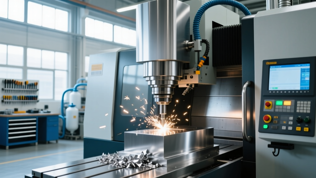
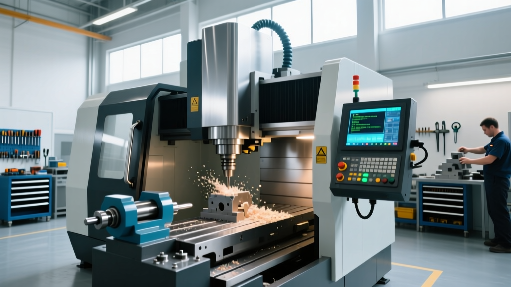
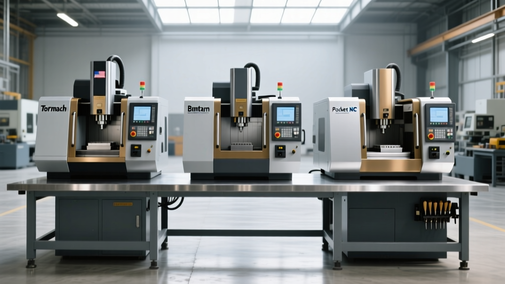
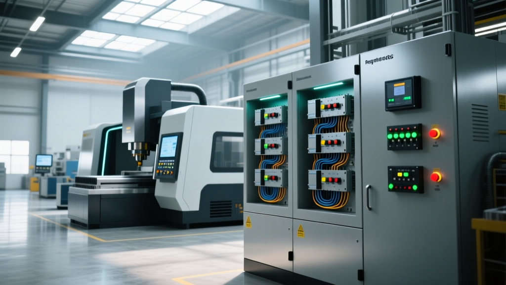
While high-resolution pictures of CNC machines on manufacturer brochures highlight sleek sheet metal, ergonomic pendants, and massive working envelopes, they entirely obscure the most critical factor in a successful installation: the electrical infrastructure. In 2026, as machine shops integrate high-torque direct-drive spindles, active front-end (AFE) rectifiers, and IoT power monitoring, treating the electrical setup as a mere 'plug-and-play' afterthought leads to catastrophic encoder failures, thermal faults, and utility penalty fees.
This guide bypasses the visual aesthetics and dives directly into the electrical engineering requirements for modern CNC deployment, focusing on 3-phase sizing, harmonic mitigation, and regenerative bus architectures.
Sizing the Supply: kVA, Inrush, and NEC Compliance
A common failure point in shop setups is sizing the transformer and main breaker based on the machine's continuous running current rather than its peak inrush and acceleration demands. Modern CNCs utilize large servo drives that can draw 150% to 200% of Full Load Amps (FLA) during rapid axis acceleration or heavy roughing cycles.
Per the National Electrical Code (NEC NFPA 70), branch circuit conductors and overcurrent protection for continuous motor loads must be sized at 125% of the motor FLA. However, CNC control transformers and servo drives require specific kVA (kilovolt-ampere) calculations to account for power factor (PF) inefficiencies during peak cutting.
2026 Machine Power Matrix: Sizing & Wire Gauge
The following matrix provides baseline electrical requirements for three highly prevalent CNC platforms. Wire gauges assume THHN/THWN-2 copper in a 30°C ambient environment with a maximum 100-foot run from the disconnect to the machine cabinet.
| Machine Model | Voltage / Phase | Required kVA | FLA (Approx) | Main Breaker | Min. Wire Gauge (AWG) |
|---|---|---|---|---|---|
| Haas VF-2SS | 230V / 3-Phase | 40 kVA | 40A | 60A | 6 AWG |
| Mazak Integrex i-200 | 480V / 3-Phase | 65 kVA | 70A | 100A | 3 AWG |
| DMG MORI NLX 2500 | 400V / 3-Phase | 75 kVA | 85A | 125A | 2 AWG |
Harmonic Mitigation and IEEE 519 Compliance
Modern CNC drives use pulse-width modulation (PWM) to control servo motors. While highly efficient, the rectifier stage of these drives draws non-sinusoidal current, injecting harmonic distortion back into the shop's electrical grid. This Total Harmonic Distortion (THD) causes overheating in neutral wires, premature transformer failure, and interference with sensitive metrology equipment like CMMs.
According to Fluke's power quality guidelines and the IEEE 519-2022 standard, industrial facilities must maintain voltage THD below 5% at the point of common coupling (PCC). In 2026, utility companies are increasingly installing smart meters that penalize shops with poor power factors and high harmonic injection.
Solutions for Harmonic Distortion
- Line Reactors (3% to 5% Impedance): The most cost-effective baseline defense. Installing a 5% impedance line reactor on the main 480V input reduces current THD from ~80% down to ~35%, protecting the CNC's internal power supply.
- Active Harmonic Filters (AHF): For shops running 5+ CNCs on a single 200kVA transformer, AHFs inject inverse harmonic currents to cancel out distortion, achieving <5% THD. Expect to invest $12,000–$18,000 per 100A AHF module.
- Active Front Ends (AFE): Premium 2026 CNC models from brands like Heller and Grob now offer AFE drives natively. AFEs use IGBTs on the input stage to draw near-perfect sinusoidal current and can operate at a unity power factor (1.0 PF).
The 2026 Standard: Regenerative DC Bus Architectures
Historically, when a CNC axis decelerated or a spindle braked, the kinetic energy was converted to heat and dumped into massive aluminum braking resistors on top of the control cabinet. This wasted energy and increased shop HVAC loads.
The current innovation standard leverages regenerative DC bus sharing. As highlighted by the U.S. Department of Energy's Advanced Manufacturing Office, modern motor systems are shifting toward regenerative topologies. In a shared DC bus architecture (common in Siemens SINAMICS S120 and FANUC Series 30i-B systems), the braking energy from the X-axis motor is instantly transferred via the DC bus to the Z-axis motor as it accelerates upward against gravity.
'By eliminating external braking resistors and utilizing regenerative power sharing, multi-axis machining centers reduce peak electrical demand by up to 22%, fundamentally altering the shop's peak-demand billing tier.' — 2026 Industrial Energy Audit Report
Grounding Topologies: Eliminating the 'Ghost' Voltage
The most frequent cause of unexplainable spindle encoder faults and 'following error' alarms is improper grounding. CNC control logic operates on 5V and 24V DC, making it hyper-sensitive to high-frequency electrical noise riding on the ground plane.
The Star Grounding Mandate
Never daisy-chain the ground wires from your CNC to a coolant pump, chip conveyor, or adjacent welder. You must utilize a Star Grounding Topology:
- Drive a dedicated copper-clad steel ground rod (minimum 8 feet) directly outside the machine foundation.
- Run an isolated, insulated ground wire (green with yellow stripe) directly from the rod to the machine's main PE (Protective Earth) busbar.
- Ensure the resistance to earth is strictly less than 1 Ohm. Measure this using a 3-point fall-of-potential ground tester, not a standard multimeter.
- Bond the machine's sheet metal enclosure to the PE busbar using braided copper straps to create a Faraday cage effect, blocking RF interference from nearby VFDs or EDM machines.
Summary of Deployment Prerequisites
Before the rigging team uncrates the equipment, the shop electrician must verify:
- Transformer kVA exceeds the sum of all machine requirements plus a 20% future expansion buffer.
- Ground resistance is tested and certified at < 1 Ohm.
- Line reactors or AHFs are installed if the shop grid THD exceeds 5%.
- Voltage under full load remains within ±5% of the machine's nameplate rating.
Understanding the electrical anatomy behind the machine is what separates a high-margin, lights-out manufacturing cell from a shop plagued by downtime and electrical gremlins.