3-Axis Dental CNC Machine Setup: Capabilities & Best Practices
Master 3-axis dental CNC machine setup with our operator training guide. Learn zirconia milling capabilities, tool calibration, and puck fixation.
Core Capabilities and Geometric Limits of 3-Axis Dental Mills
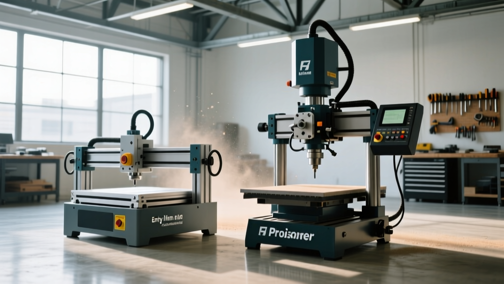
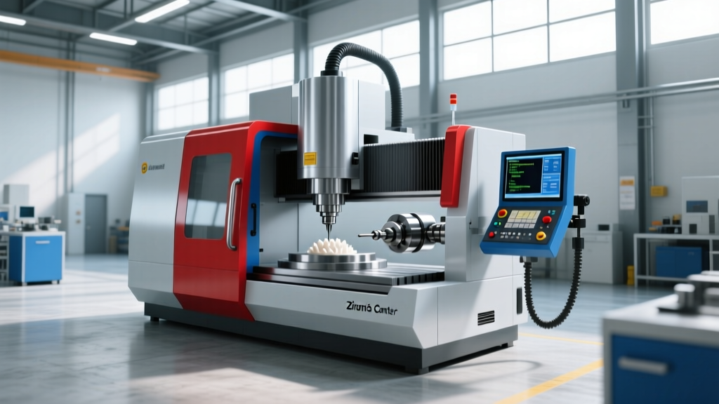
Operating a 3-axis dental CNC machine requires a precise understanding of its kinematic constraints and material compatibility. Unlike 5-axis simultaneous mills, a 3-axis configuration restricts the cutting tool to linear X, Y, and Z movements while the workpiece remains statically fixed. This architecture excels in high-volume production of standard restorations but demands rigorous operator training to navigate its geometric blind spots.
Material Compatibility: Dry vs. Wet Milling Constraints
The vast majority of 3-axis dental CNC machines on the market (such as the Roland DWX-52D series or imes-icore CORiTEC One) are configured as dry mills. This dictates strict material limitations:
- Y-TZP Zirconia (Yttria-Stabilized Tetragonal Zirconia Polycrystal): Fully supported. Operators can mill pre-sintered zirconia discs ranging from 10mm to 25mm in thickness, achieving flexural strengths up to 1200 MPa post-sintering.
- PMMA and Wax: Fully supported. Ideal for provisional restorations, diagnostic wax-ups, and casting patterns.
- PEEK (Polyetheretherketone): Supported, but requires dedicated toolpaths and specialized extraction systems due to the stringy, thermoplastic nature of the swarf.
- Lithium Disilicate (e.g., IPS e.max CAD): NOT supported on dry 3-axis mills. Glass-ceramics require continuous water coolant to prevent thermal micro-fractures and catastrophic tool wear. Attempting to mill lithium disilicate on a dry 3-axis spindle will destroy the spindle bearings and shatter the block.
Operator Setup Protocol: Puck Fixation and Tool Calibration
Dimensional accuracy in dental milling—where marginal gaps must remain under 50 microns for proper cementation—relies entirely on the rigidity of the setup. A failure in puck fixation is the leading cause of scrapped restorations.
Step 1: Adapter Ring and Puck Matching
Standard dental zirconia discs utilize a 98mm outer diameter, but their edge profiles vary. Discs are manufactured with either a flat edge or a stepped edge (typically a 2mm or 3mm step). Operators must match the machine's adapter ring to the disc profile. If a stepped disc is loaded into a flat adapter ring, the radial set screws will grip the thin step rather than the main body. Under the lateral forces of a roughing pass (often exceeding 150 N), the disc will slip, causing a Z-axis shift that ruins the internal fit of the crown.
Step 2: Chemical Fixation Best Practices
For thinner discs (10mm-14mm) or PMMA pucks, mechanical clamping is often supplemented or replaced by chemical adhesion to the adapter ring. Use a medium-viscosity cyanoacrylate-based lab adhesive. Apply exactly three 10mm beads spaced 120 degrees apart on the adapter ring seating surface. Avoid high-viscosity gap-filling glues, as they introduce a 0.1mm to 0.2mm Z-axis offset that the CAM software cannot compensate for.
Step 3: Spindle Thermal Stabilization
Dental spindles operate at extreme speeds (up to 60,000 RPM). Cold starts cause thermal expansion of the spindle shaft and bearings during the first 15 minutes of operation, altering the Z-axis tool length offset by up to 20 microns. Always execute a 5-minute spindle warm-up routine at 20,000 RPM before initiating the first milling job of the day.
Toolpath Strategies and Tool Wear Matrix
Tool selection for 3-axis dental milling is governed by the shank diameter (typically 2.35mm or 3.0mm) and the required detail resolution. Diamond-coated tungsten carbide tools are mandatory for zirconia; standard carbide tools will dull within a single crown.
According to research published on dental CAD/CAM accuracy, tool wear directly correlates with marginal discrepancy (National Institutes of Health). Operators must adhere to strict replacement thresholds rather than waiting for visible tool failure.
| Tool Type | Shank / Tip Diameter | Primary Application | Max Lifespan (Zirconia) | Max Lifespan (PMMA) |
|---|---|---|---|---|
| Diamond Ball End Mill | 2.35mm shank / 2.0mm tip | Roughing, bulk material removal | 25-30 units | 150+ units |
| Diamond Tapered Ball | 2.35mm shank / 1.0mm tip | Semi-finishing, occlusal anatomy | 15-20 units | 100+ units |
| Diamond Tapered Ball | 2.35mm shank / 0.6mm tip | Margin finishing, deep embrasures | 8-12 units | 60+ units |
| Flat End Mill | 3.0mm shank / 2.0mm tip | PMMA block facing, sprue cutting | N/A | 80+ units |
Troubleshooting Common 3-Axis Milling Defects
When a 3-axis dental CNC machine produces defective output, the root cause is almost always traceable to operator setup errors or degraded machine components. Use this diagnostic framework to resolve common issues.
Defect 1: Micro-Chipping at the Cervical Margin
- Symptom: The crown margin exhibits a scalloped, chipped edge under 10x magnification, leading to poor seating and open margins.
- Cause A (Tooling): The 0.6mm finishing tool has exceeded its lifespan, and the diamond grit has worn smooth, causing it to tear rather than cut the pre-sintered zirconia.
- Cause B (Machine): Spindle runout exceeds 0.005mm. This causes the tool tip to orbit, effectively making a 0.6mm tool act like a 0.7mm tool, gouging the margin.
- Resolution: Replace the finishing tool. If the defect persists, measure spindle runout with a dial indicator mounted on the machine bed. If runout is >0.005mm, schedule a spindle bearing replacement. Additionally, reduce the finishing feed rate by 20% in the CAM software to lower lateral cutting forces.
Defect 2: Internal Crown Misfit (High Spots)
- Symptom: The restoration seats on the die but rocks, or requires excessive force to seat, indicating interference in the internal intaglio surface.
- Cause: Z-axis thermal drift or incorrect tool length calibration. If the operator calibrated the tool length while the spindle was cold, thermal expansion during the 45-minute milling cycle will cause the tool to cut deeper than programmed, altering the internal coping thickness.
- Resolution: Implement the mandatory 5-minute spindle warm-up protocol before tool calibration. Ensure the machine's automatic tool length sensor is free of zirconia dust, which can artificially inflate the measured tool length by 10-15 microns. Use compressed air to blast the sensor pad before every calibration cycle.
Defect 3: Adapter Ring Slippage
- Symptom: The crown is completely misaligned on the Y or X axis, or the disc breaks free from the adapter during the roughing pass.
- Cause: Inadequate torque on the radial set screws, or using a flat adapter for a stepped disc.
- Resolution: Verify the disc profile. Apply exactly 1.5 Nm of torque to the set screws using a calibrated torque screwdriver. Hand-tightening is insufficient for the 30,000+ RPM cutting forces generated during zirconia roughing. The U.S. Food and Drug Administration emphasizes that manufacturing deviations in dental restorations often stem from improper equipment calibration and setup protocols.
Maintenance and Environmental Controls
The operational environment of a 3-axis dental CNC machine directly impacts its lifespan and accuracy. Pre-sintered zirconia generates a fine, abrasive dust that is highly destructive to linear guideways and ball screws if the machine's extraction system is compromised.
Operators must verify that the vacuum extraction system maintains a minimum airflow of 250 cubic feet per minute (CFM). Filter bags must be emptied when they reach 75% capacity; a clogged filter reduces suction velocity, allowing heavy zirconia particles to settle inside the machine enclosure rather than being evacuated. Furthermore, linear guideways should be purged and re-lubricated with ISO VG 68 way oil every 500 operating hours to prevent the abrasive dust from scoring the bearing surfaces. Proper adherence to these setup and maintenance protocols ensures that a 3-axis dental CNC machine consistently produces restorations that meet the stringent clinical standards for CAD/CAM dental ceramics.