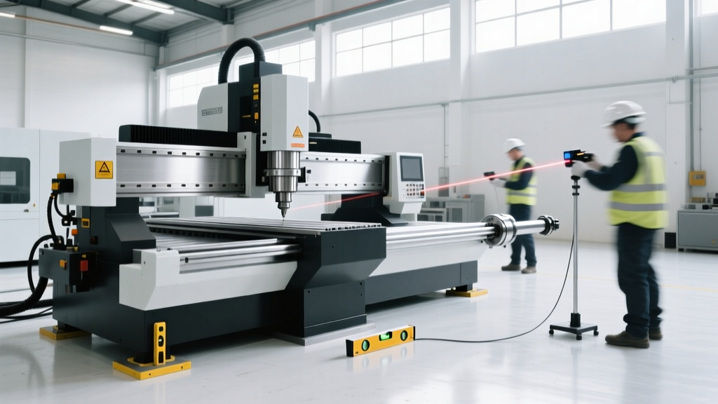
3-Axis CNC Setup: CNC Machine Movers and Initial Calibration
Master 3-axis CNC setup after the CNC machine movers leave. Learn foundation specs, precision leveling, tramming, and NAS 979 capability verification.
The Rigging Handoff: Where Setup Actually Begins
Professional CNC machine movers utilize hydraulic gantries, toe jacks, and heavy-duty machinery skates (such as Hilman 8-ton rollers) to position vertical machining centers (VMCs) onto their shop floor pads. Once the rigging crew removes the skates and lowers the machine, their job is done, but the operator's critical setup phase begins. A 6,300 lb Haas VF-2SS or a 9,500 lb Doosan DNM 5700 can easily suffer base casting twist if lowered unevenly onto an unverified foundation. This twist permanently compromises the 3-axis geometric envelope before the first chip is ever cut.
While CNC machine movers typically charge between $1,500 and $4,500 for local transport and placement, their scope ends at physical positioning. It is the operator's responsibility to verify that the handoff did not introduce stress into the machine's cast iron base. According to OSHA material handling guidelines, improper load distribution during the final lowering phase is a primary cause of equipment misalignment and subsequent shop floor accidents.
⚠️ Warning: The 72-Hour Concrete Cure RuleNever allow movers to place a 3-axis CNC directly onto newly poured epoxy grout or concrete pads that have not cured for a minimum of 72 hours. Premature loading causes micro-subsidence, guaranteeing the machine will fall out of level within the first month of operation.
Foundation Dynamics and Vibration Isolation
Before initiating the leveling sequence, verify the foundation's load-bearing capacity. 3-axis CNC machines generate significant dynamic forces during rapid traverses and heavy roughing cycles. If the floor deflects, the machine's geometry shifts.
| Machine Class | Example Model | Approx. Weight | Min. Floor PSI | Mounting Requirement |
|---|---|---|---|---|
| Light Duty / Prototyping | Tormach 1100MX | 1,600 lbs | 2,000 PSI | Neoprene isolation pads |
| Standard Production VMC | Haas VF-2SS | 6,300 lbs | 3,000 PSI | Adjustable leveling feet + anchors |
| Heavy Duty / Hard Milling | Doosan DNM 5700 | 9,500 lbs | 4,000 PSI | Epoxy grout + wedge anchors |
Precision Leveling: The 4-Point Sequence
Do not rely on standard carpenter's bubble levels or digital inclinometers with 0.1-degree resolutions. 3-axis CNC setup requires a precision machinist level, such as the Starrett 199Z Master Precision Level, which resolves to 0.0005 inches per foot. The goal is not just to make the machine sit flat, but to remove internal casting stress.
Step-by-Step Leveling Procedure
- Clean the Way Covers and Table: Wipe down the X-axis table and Y-axis saddle with a lint-free cloth and isopropyl alcohol. Any metal chip or dust particle will skew the level.
- Initial X-Axis Sweep: Place the Starrett level parallel to the X-axis travel. Jog the table to the extreme left, record the bubble position, then jog to the extreme right. Adjust the front-left and front-right leveling feet until the bubble remains centered across the entire travel.
- Initial Y-Axis Sweep: Rotate the level 90 degrees to align with the Y-axis. Move the saddle forward and backward. Adjust the rear leveling feet to center the bubble.
- The Cross-Check: Return to the X-axis. The act of adjusting the Y-axis often shifts the X-axis geometry. Repeat the sweeps, making micro-adjustments (1/8th of a turn on the leveling feet) until both axes hold the 0.0005 in/ft tolerance simultaneously.
- Anchor Tensioning: Once leveled, torque the floor anchor bolts to the manufacturer's specification (typically 65-85 ft-lbs for standard 5/8-inch wedge anchors). Re-check the level immediately after torquing, as bolt tension frequently pulls the base casting out of alignment.
Diagnosing and Correcting Base Twist
If you cannot achieve level on both axes simultaneously, the CNC machine movers likely dropped the machine onto a high corner, inducing base twist. To diagnose this, place a dial indicator (e.g., Mitutoyo 2046F with 0.0001-inch resolution) on the table and sweep the spindle nose across the X-axis. If the indicator shows a consistent ramp that cannot be eliminated by adjusting the leveling feet, the casting is twisted.
The Fix: Loosen all anchor bolts and leveling feet. Lift the machine slightly using a hydraulic toe jack placed under the reinforced lifting lugs—not under the sheet metal or chip conveyor trough. Insert precision steel shims under the affected corner's mounting pad, lower the machine, and restart the 4-point leveling sequence. Never force a twisted casting into level using only the anchor bolts; this stores potential energy in the iron that will release as thermal growth occurs during operation.
Expert Insight on Thermal Growth: Cast iron expands at a rate of approximately 6.5 microinches per inch per degree Fahrenheit. A 3-axis VMC located near a loading dock door or in direct sunlight from a skylight will experience uneven thermal growth. Always perform your final leveling and tramming verification during the shop's stable ambient temperature window, typically between 2:00 AM and 5:00 AM, or ensure the shop's HVAC system has maintained a 68°F (20°C) baseline for at least 12 hours prior to calibration.
Squaring the 3-Axis Envelope (Tramming)
With the machine leveled and anchored, the next step is verifying the spindle's perpendicularity to the table. This dictates the machine's ability to hold flatness and true 90-degree angles.
- X-Z Plane Tram (Left/Right): Mount a 12-inch tramming arm in the spindle with a dial indicator at the tip. Sweep left to right across the table. Acceptable tolerance for standard 3-axis milling is 0.0002 inches across the 12-inch sweep. If out of spec, the column may need to be shimmed at the base, or the spindle head gibs require adjustment.
- Y-Z Plane Tram (Front/Back): Sweep the indicator front to back. This verifies the column's squareness to the Y-axis travel. Deviations here often indicate uneven wear on the Y-axis linear guideways or a twisted column resulting from an improper rigging handoff.
Capability Verification: The NAS 979 Test Cut
Geometric alignment on paper means nothing until verified in metal. To validate the setup performed after the CNC machine movers departed, execute the NAS 979 Circle-Diamond-Square test. This standardized test evaluates the machine's volumetric accuracy, backlash compensation, and circular interpolation capabilities.
Test Cut Parameters for Aluminum 6061-T6:- Tooling: 1/2-inch 3-flute carbide endmill.
- Spindle Speed: 8,000 RPM.
- Feed Rate: 40 IPM.
- Depth of Cut: 0.100-inch axial, 0.050-inch radial.
- Evaluation: Measure the square for 90-degree corner accuracy (tolerance ±0.0005 inches). Measure the circle for axis reversal backlash (out-of-roundness should be less than 0.0003 inches on a properly tuned 3-axis VMC). Refer to the official Haas service manuals or your specific OEM documentation for parameter adjustments to ball screw backlash compensation if the circle test shows lobing at the quadrant transitions.
Frequently Asked Questions
Do I need to re-level my 3-axis CNC after the first month of operation?
Yes. The foundation, anchor bolts, and machine casting undergo a settling period during the first 30 to 60 days of dynamic loading. Schedule a mandatory re-leveling and tramming verification at the 45-day mark, and subsequently every six months as part of your preventive maintenance protocol.
Can CNC machine movers transport a machine with the column extended?
Never. The Y-axis saddle and Z-axis spindle head must be mechanically locked in their center travel positions, and the axes must be blocked with high-density polyurethane foam or custom wooden shipping brackets. Transporting a VMC with the column extended to the top of its Z-travel creates a massive lever arm that can snap the cast iron column or destroy the Z-axis linear guideways if the transport truck hits a pothole.
What is the most common mistake operators make after the rigging crew leaves?
Failing to remove the cosmoline and rust-preventative coatings from the linear guideways and ball screws before applying way oil. If an operator initiates the auto-lube system without manually cleaning the ways, the cosmoline mixes with the way oil to form an abrasive sludge that accelerates guideway wear and causes stick-slip friction during low-speed contouring operations.