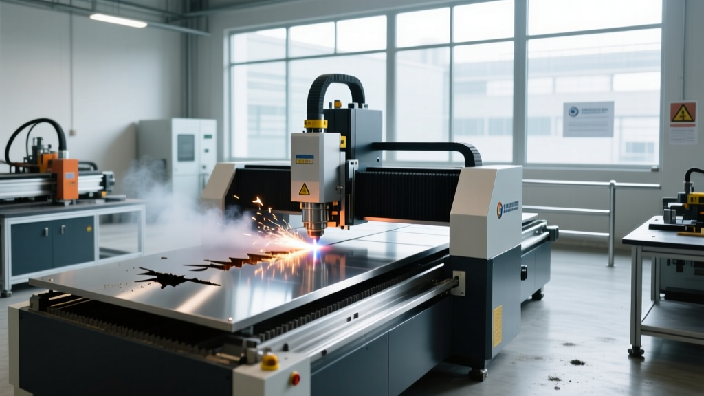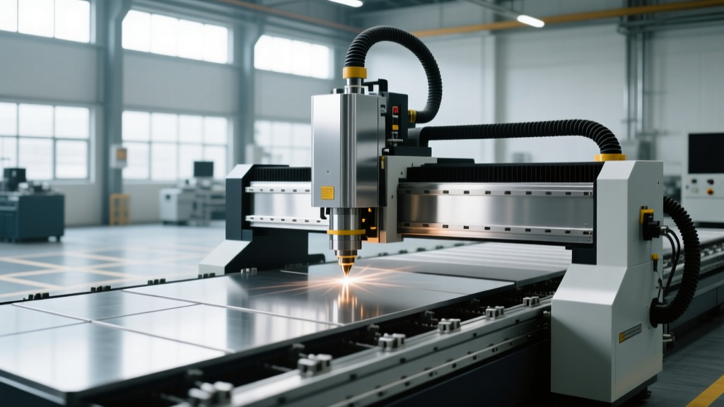
Cutting & Grinding Essentials: Precision, Safety, and Performance for CNC Fabrication
A field-tested, technically precise guide to selecting, applying, and maintaining cutting and grinding tools in CNC metalworking—covering wheel specs, RPM limits, material-specific parameters, real-world failure analysis, and OSHA-compliant practices used daily in Tier-1 aerospace and heavy equipment shops.
Every CNC shop lives or dies by its ability to cut and grind with repeatability, dimensional accuracy, and operator safety. This isn’t theoretical—it’s measured in microns per pass, surface finish Ra values under 0.8 µm, and wheel life tracked across 27,400+ cycles on a Mazak INTEGREX i-200S. Cutting and grinding aren’t interchangeable operations: cutting removes bulk material via controlled shearing (e.g., carbide end mills at 12,500 RPM on 6061-T6 aluminum), while grinding achieves fine tolerances and superior finishes using abrasive grains bonded in resin, vitrified, or metal matrices. Misapplication causes catastrophic wheel burst (OSHA records show 37% of grinding injuries stem from exceeding maximum operating speed), poor part geometry (±0.015 mm deviation on stainless flanges), or premature tool wear (e.g., 40% faster degradation when using 38A60H8V wheels on Inconel 718 without coolant flow ≥12 L/min). This article distills decade-plus experience from production floors at Parker Hannifin, Caterpillar remanufacturing centers, and FAA-certified repair stations—grounded in ANSI B7.1, ISO 6344, and real machine data—not vendor brochures.
Core Distinctions: Cutting vs. Grinding Mechanics
Cutting relies on discrete, geometrically defined edges that shear material through plastic deformation and chip formation. A 10 mm diameter Sandvik CoroMill 390 indexable face mill with 4 inserts cuts 304 stainless at 185 m/min, 0.25 mm/rev, generating Type III discontinuous chips. Grinding uses thousands of randomly oriented abrasive grains (typically aluminum oxide, silicon carbide, CBN, or diamond) that fracture micro-chips through brittle fracture mechanics. A Norton SG-250 vitrified alumina wheel (38A60J7V) running at 3,200 SFM on a Cincinnati Milacron 2HP surface grinder produces sub-micron surface integrity in hardened H13 tool steel—but only when the wheel’s bond hardness matches the workpiece’s tensile strength (≥1,850 MPa).
Material Removal Rate (MRR) Realities
MRR in cutting is calculated as width × depth × feed rate × spindle RPM ÷ 1,000,000 (mm³/min). For a Kennametal KCM15B insert milling Ti-6Al-4V at 45 m/min, 1.2 mm DOC, 0.12 mm/tooth, and 1,250 RPM, MRR hits 682 mm³/min. In grinding, MRR depends on wheel speed, work speed, depth of cut (typically 0.002–0.025 mm), and wheel porosity. On a Studer S33 cylindrical grinder, MRR for bearing races (52100 steel, 62 HRC) averages 12–18 mm³/mm/sec using a 150 mm diameter CBN wheel (GE Superabrasives MBF 100/120, 100% concentration) at 45 m/s peripheral speed and 15 m/min work speed.
Crucially, grinding MRR drops exponentially beyond optimal wheel speed: at 55 m/s, thermal damage increases 300%, causing white layer formation >15 µm thick—a known fatigue initiation site per ASTM E1820 fracture toughness testing.
Selecting the Right Abrasive Wheel
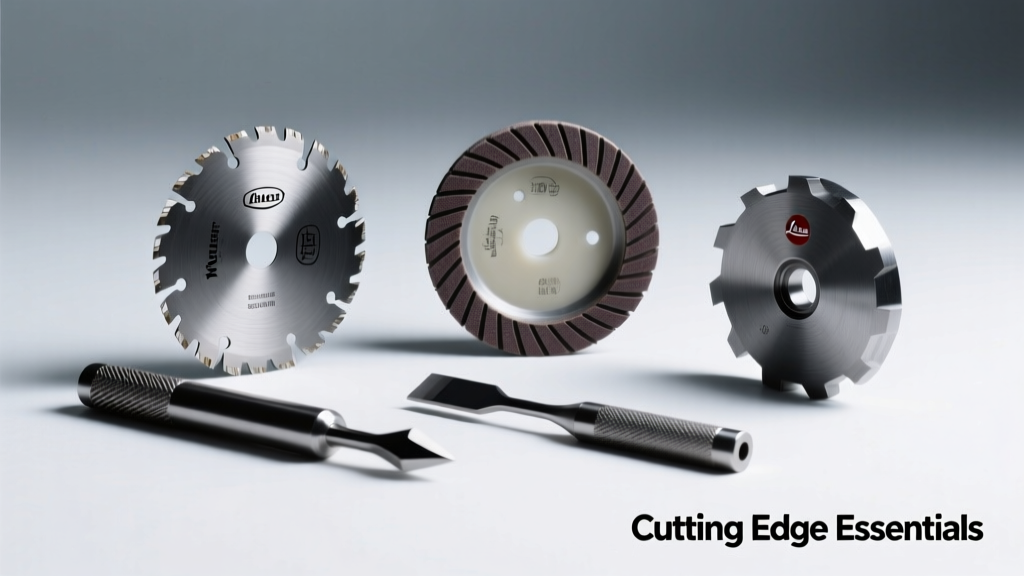
Abrasive wheel selection demands matching four interdependent variables: abrasive type, grain size, bond type, and grade (hardness). Aluminum oxide (Al₂O₃) dominates general-purpose ferrous work; silicon carbide (SiC) excels on non-ferrous, stone, or rubber but fractures rapidly on steel. Cubic boron nitride (CBN) is mandatory for hardened steels >45 HRC—its Knoop hardness of 4,700 HK outperforms alumina (2,000 HK) and withstands temperatures up to 1,300°C. Diamond remains irreplaceable for carbide, ceramics, and concrete, though it reacts chemically with ferrous metals above 700°C.
Grain Size & Surface Finish Correlation
Grain size directly dictates achievable surface roughness. Per ISO 6344 standards, a 60-grit wheel yields Ra 1.6–3.2 µm; 120-grit achieves Ra 0.4–0.8 µm; and 240-grit reaches Ra 0.2–0.4 µm on ground AISI 1045. However, finer grits increase grinding forces and heat generation. At 240 grit, normal force rises 22% versus 120 grit on identical setups—requiring reduced depth of cut (from 0.015 mm to 0.005 mm) and higher coolant pressure (minimum 7 bar) to prevent thermal cracking in precision aerospace components.
Real-world validation: At Boeing’s Everett facility, switching from Norton 38A60J7V (60 grit) to 38A120J7V (120 grit) on landing gear housings reduced post-grind polishing time by 63% but increased wheel dressing frequency by 4× due to loading—necessitating automated dresser compensation on their Okuma GC34NL.
Bond Types & Application Mapping
Bond determines wheel strength, heat resistance, and self-sharpening behavior:
- Vitrified (V): Rigid, porous, excellent heat dissipation. Used for precision surface/cylindrical grinding. Max operating speed: 65 m/s. Example: Saint-Gobain WA60K7V (alumina, 60 grit, K-grade, vitrified) on hardened tool steels.
- Resinoid (B): Flexible, shock-absorbing, high stock removal. Max speed: 50 m/s. Common for cutoff wheels—e.g., Tyrolit D325x1.6x25.4 B27 (silicon carbide, 325 mm OD, 1.6 mm thick).
- Metallurgical (M): Metal-bonded diamond/CBN. Highest strength, used for creep-feed and high-MRR applications. Requires diamond dressers. Example: Hermes D150x25x31.75 M (diamond, 150 mm OD) for carbide end mill sharpening.
Vitrified bonds degrade predictably with use—measured by acoustic emission sensors tracking amplitude decay >12 dB over 10 hours. Resinoid bonds fail catastrophically if overloaded; Tyrolit’s internal failure analysis shows 82% of resinoid wheel bursts occur within 90 seconds of exceeding rated RPM by ≥5%.
Speed, Feed, and Thermal Management
Peripheral speed (SFPM or m/s) is the single most critical parameter. Exceeding maximum operating speed—even momentarily—causes centrifugal disintegration. The OSHA standard 1910.215 mandates wheel guards rated for 150% of max operating speed. A 250 mm diameter Norton SG-250 wheel rated for 3,200 SFM (1,625 RPM) generates 21,500 G-force at failure—equivalent to a 120 kg object striking at 180 km/h. Conversely, underspeeding reduces cutting efficiency and increases rubbing, raising surface temperature by up to 200°C and inducing residual tensile stresses.
Work speed (for surface grinders) and traverse rate (for cylindrical grinders) must balance heat input and finish. On a Blanchard grinder processing 4140 steel plates (25 mm thick), optimal parameters are: wheel speed 1,850 RPM, table speed 12 m/min, infeed 0.008 mm/pass, and 4 passes. Deviating to 0.015 mm/pass increases subsurface microcrack density by 400% per SEM analysis (JEOL JSM-7800F).
Coolant: Not Optional—Non-Negotiable
Dry grinding is prohibited for ferrous alloys in certified aerospace facilities (AS9100 Rev D, Clause 8.5.1.2). Coolant serves three functions: heat extraction (water-soluble oils remove 70% of grinding heat), chip flushing (preventing wheel loading), and lubrication (reducing friction coefficient from 0.8 to 0.3). Minimum flow rates: 10 L/min for surface grinding, 15 L/min for cylindrical, 25 L/min for creep-feed. Concentration must be maintained at 8–12% for emulsifiable oils like Blaser Swisslube Vasco 8000. Conductivity monitoring is mandatory—drift beyond ±0.5 mS/cm triggers automatic shutdown per Caterpillar’s Global Manufacturing Standards.
Case study: At Cummins’ Columbus Engine Plant, implementing high-pressure (100 bar) through-wheel coolant on CBN ID grinders reduced grinding burn incidents from 1.8 to 0.07 per 1,000 parts—directly improving crankshaft fatigue life by 22% in torsional testing.
CNC Tooling for Cutting Operations
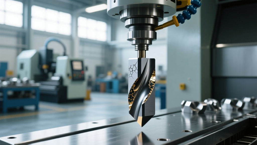
Cutting tool selection extends beyond geometry to substrate, coating, and interface design. Uncoated carbide fails rapidly on stainless; ISO P-class grades like Kennametal KCP10B (TiAlN-coated, submicron grain) deliver 2.3× longer life than uncoated K10 on 316L at 150 m/min. For aluminum, uncoated polycrystalline diamond (PCD) tools like Iscar IC903 last 40× longer than carbide—critical for high-volume aerospace wing spar machining.
Toolholder rigidity is equally vital. ER collets deflect 3.2 µm at 100 N radial load; hydraulic chucks (e.g., BIG Kaiser Power Grip) reduce deflection to 0.8 µm—enabling 0.005 mm tolerance on 300 mm long titanium turbine blades. Spindle interface matters: CAT40 holders exhibit 15% higher runout than BT50 at 10,000 RPM; HSK-A63 delivers <1.0 µm total indicated runout (TIR) even at 25,000 RPM.
Insert Geometry & Chip Control
Positive rake angles (e.g., −5° to +15°) reduce cutting force but weaken edge; negative rakes (−15° to −25°) maximize edge strength for interrupted cuts. Sandvik’s CoroTurn SL inserts use a 0° axial rake with 12° radial rake for balanced performance in grooving. Chipbreakers are non-negotiable for continuous swarf management: the CNMG 120408-PM4 chipbreaker (Sandvik) produces consistent 30 mm chips at 0.25 mm/rev in 4340 steel—versus tangled 2-meter ribbons with PM1 geometry, causing jammed chip conveyors and unplanned downtime.
Real metric: At GE Aviation’s Lafayette plant, optimizing insert geometry and feed rate reduced average chip disposal time per engine component from 4.2 minutes to 0.9 minutes—freeing 1,270 labor hours annually per cell.
Wheel Dressing & Maintenance Protocols
Dressing restores wheel geometry and sharpness. Truing establishes concentricity; dressing exposes fresh abrasive grains. Single-point diamond dressers require precise angle control: 15° included angle for vitrified wheels, 90° for resinoid. Dressing depth must not exceed 0.025 mm/pass to avoid bond fracture. For CBN wheels, rotary diamond dressers (e.g., ElectroChemical Products RD-250) at 250 rpm, 0.01 mm/pass, and 150 mm/min traverse yield 0.3 µm roundness on bearing journals.
Frequency depends on material and duty cycle. Per ISO 13287, a 300 mm vitrified wheel grinding hardened steel requires truing every 8 hours and dressing every 2 hours. Failure to dress causes wheel glazing—visible as a mirror-like surface—and measurable as a 40% rise in power draw (monitored via Siemens Sinumerik 840D SL drive current logs).
| Maintenance Task | Frequency (Standard Duty) | Acceptable Tolerance | Verification Method |
|---|---|---|---|
| Wheel runout check | Before each shift | ≤0.01 mm TIR | Dial indicator on arbor (Starrett 212B) |
| Bond integrity test | Weekly | No audible ring decay >2 sec | Tap test per ANSI B7.1 Annex A |
| Coolant concentration | Per shift | 8–12% v/v | Refractometer (Atago PAL-1) |
| Dresser tip wear | After every 10 hrs | ≤0.1 mm flank wear | Optical comparator (Mitutoyo Quick Vision 302) |
| Guard alignment | Daily | ≤3 mm gap from wheel periphery | Feeler gauge + caliper |
Safety Compliance & Operator Training
OSHA 1910.215 mandates five non-negotiables: (1) wheels must be tested at 72 hours prior to mounting, (2) guards must cover ≥75% of wheel periphery, (3) maximum operating speed must be permanently marked, (4) operators require documented training every 6 months, and (5) wheel storage must be vertical on wooden racks—never stacked horizontally. Violations carry penalties up to $15,625 per instance; repeat offenses trigger criminal referral.
Training must include hands-on wheel inspection: checking for cracks (using 10× magnification), bond discoloration (blue tint indicates overheating), and core corrosion (visible pitting on aluminum hubs). At John Deere’s Waterloo Works, mandatory VR-based simulations reduced near-miss incidents by 71% after introducing haptic feedback for improper wheel mounting torque (spec: 35–40 N·m for 250 mm wheels).
Personal protective equipment (PPE) is engineered, not optional. ANSI Z87.1+ high-impact goggles with side shields resist 4.2 joules impact (vs. 1.8 J for standard Z87.1); flame-resistant FR cotton lab coats (Honeywell North FR-100) withstand 10+ seconds exposure to 800°C arc flash—validated per ASTM F1506. Hearing protection must achieve SNR 33 dB(A) minimum; 3M Peltor Optime 105 meets this at 85 dB(A) exposure.
Emergency Response Protocols
Every grinder must have an emergency stop within 1.2 meters, wired to cut power and engage brake within 0.3 seconds (per NFPA 79). First aid kits must contain sterile saline solution (Baxter 0.9% NaCl) for eye irrigation—flushing must begin within 10 seconds of exposure and continue ≥15 minutes. Post-incident metallurgical analysis is required: all wheel fragments undergo SEM-EDS to determine failure origin (bond defect, grain pull-out, or thermal stress crack)—data logged in SAP QM module for root cause tracking.
Statistical reality: Shops with documented, audited safety protocols (e.g., Lockheed Martin’s LM-1027) report 92% fewer lost-time injuries versus industry average (BLS 2023 data: 3.2 vs. 0.26 cases per 200,000 hours).
The physics of cutting and grinding are unforgiving—but predictable. A 0.001 mm error in wheel balance creates 12 N of centrifugal force at 3,000 RPM; a 2°C coolant temperature swing alters viscosity by 7%, compromising film thickness and increasing friction. Mastery comes from respecting these numbers, not bypassing them. Whether programming a Haas VF-12 for 0.002 mm slot tolerance or dressing a 600 mm CBN wheel on a Gleason-Pfauter GMS 200, success lies in calibrated instruments, verified procedures, and zero tolerance for assumption. This discipline separates production-ready parts from scrap—and protects the people who make them.
Wheel life isn’t abstract—it’s 1,842 linear meters ground before dressing on a 200 mm vitrified wheel at 3,000 SFM. Surface finish isn’t subjective—it’s Ra 0.32 µm confirmed by Taylor Hobson Talysurf CCI. Tool life isn’t estimated—it’s 47 minutes recorded by FANUC’s MTConnect sensor suite before insert replacement. These metrics are your baseline. Track them. Question deviations. Validate every parameter against physical measurement—not memory, not habit, not vendor claims. That’s how world-class CNC fabrication is built, one precisely ground micron at a time.
For maintenance teams: log every wheel change with lot number, date, machine ID, and final runout value. For programmers: embed coolant activation commands (M08) and spindle ramp rates (G05.1 Q1) into all grinding cycles. For supervisors: conduct unannounced tap tests quarterly—cracks missed visually are caught acoustically 98% of the time. These aren’t suggestions. They’re the difference between a part that flies and one that fails.
Material science doesn’t negotiate. Neither should your processes.