CNC Machine Laser Calibration: Troubleshooting Beam Misalignment
Master CNC machine laser calibration with this troubleshooting guide. Diagnose beam misalignment, power loss, and focal drift in fiber and CO2 systems.
Fiber lasers (1064nm) and CO2 lasers (10.6μm) demand rigorous optical alignment to maintain cut quality and dimensional accuracy. When a CNC laser cutter begins producing asymmetric kerfs, excessive dross, or incomplete penetration, the root cause frequently traces back to optical misalignment, focal drift, or capacitive sensor miscalibration. This guide provides a deep-dive troubleshooting framework for recalibrating industrial laser systems, focusing on high-power fiber resonators (e.g., IPG YLS, Raycus) and advanced cutting heads (e.g., Precitec ProCutter, Raytools).
⚠️ Class 4 Laser Safety Protocol: Before opening any optical enclosures, ensure the main resonator is locked out and keyed off. Invisible 1064nm fiber laser radiation causes instantaneous, irreversible retinal damage. Always wear wavelength-specific, OD7+ safety goggles rated for your specific laser source. Consult your facility's Laser Safety Officer (LSO) and refer to Princeton University's EHS Laser Safety Guidelines for standard operating procedures regarding Class 4 industrial systems.Symptom-to-Cause Diagnostic Matrix
Before dismantling the cutting head, map the physical defect on the workpiece to its most likely optical or mechanical failure point.
| Cut Defect / Symptom | Probable Root Cause | Diagnostic Tool | Corrective Action |
|---|---|---|---|
| Asymmetric kerf width; directional dross | Raw beam misalignment hitting nozzle wall | Thermal burn paper / Acrylic target | Adjust M1/M2/M3 kinematic mirror mounts |
| Inconsistent cut depth across Z-axis travel | Focal point drift; BCS sensor miscalibration | Capacitive sensor test block | Recalibrate Z-axis zero and ProCutter zoom |
| Slag adhesion; sudden loss of pierce power | Protective window contamination / thermal lensing | Visual inspection / Power meter | Replace fused silica window; clean with IPA |
| Circular kerf but poor edge squareness | Incorrect collimator/focusing lens ratio | Review cutting head optics specs | Swap focal length lenses to adjust Rayleigh length |
The Coarse-to-Fine Optical Alignment Protocol
Proper CNC machine laser calibration requires a systematic approach from the resonator output to the final focusing lens. According to Thorlabs' technical guide on beam alignment, utilizing a two-mirror kinematic mount system is the industry standard for steering a laser beam through a fixed optical path.
1. Resonator to Collimator Alignment
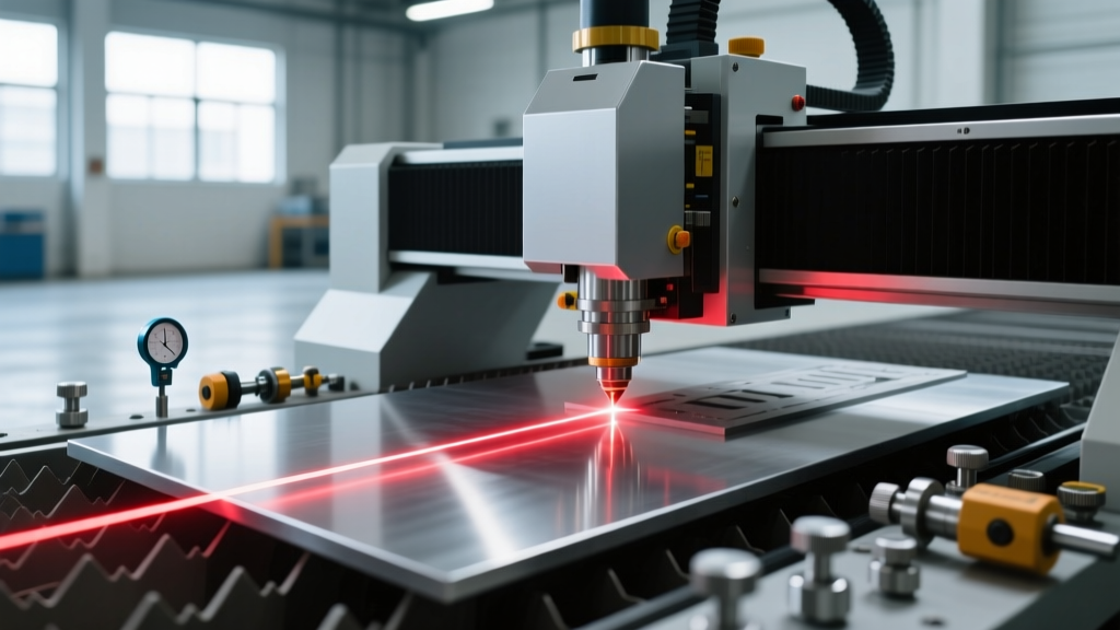
Most modern fiber laser systems utilize a visible red diode laser (typically 650nm) co-axial with the invisible 1064nm beam for coarse alignment.
- Step 1: Remove the cutting nozzle and the protective quartz window.
- Step 2: Activate the red alignment pointer from the CNC HMI (Human-Machine Interface).
- Step 3: Place a piece of thermal laser alignment paper (e.g., Kentek or Thorlabs) directly under the collimator housing. The red dot must be perfectly centered within the aperture. If it is off by more than 0.5mm, adjust the resonator output mirror mounts until centered.
2. The Burn Paper & Nozzle Concentricity Test
Once the beam passes through the collimator and focusing lens, it must exit dead-center through the nozzle orifice. Even a 0.05mm offset will cause the assist gas (Nitrogen or Oxygen) to flow asymmetrically, resulting in severe dross on one side of the cut.
- The Tape Test: Apply a piece of standard masking tape tightly over the nozzle tip.
- Pulse the Laser: Using the manual pulse function on the controller, fire a low-power, short-duration pulse (e.g., 50W power, 10ms duration, CW mode). Do not use full continuous wave power, or you will melt the nozzle.
- Measure: Remove the tape and inspect the burn mark. Use a digital caliper to measure the distance from the edge of the burn mark to the inner edge of the nozzle orifice on all four quadrants (Top, Bottom, Left, Right).
- Adjust: If the mark is off-center, use the cutting head's X/Y centering adjustment screws (usually requiring a 2mm hex key) to shift the optical axis until the burn mark is perfectly concentric with the nozzle bore.
Calibrating the Capacitive Height Sensor (BCS)
The Bus Capacitive Sensor (BCS) or Precitec capacitive controller maintains the critical standoff distance between the nozzle tip and the workpiece. If the CNC machine laser calibration for the Z-axis is drifting, the focal point will shift, causing incomplete cuts on warped sheet metal.
Recalibrating the Z-Axis Zero Point
Capacitive sensors measure the electrical capacitance between the copper/brass nozzle and the grounded steel workpiece. Over time, nozzle wear changes this capacitance profile.
- Clean the Nozzle: Remove all spatter and slag from the nozzle tip using a brass wire brush. Do not use steel wool, which can embed ferrous particles and skew capacitance readings.
- Execute the Auto-Calibrate Routine: Place a flat, unwarped 10mm steel calibration block under the head. Run the 'Capacitive Calibration' macro in the CNC software (e.g., CypCut, Beckhoff TwinCAT). The head will touch off the block to establish mechanical zero, then retract to calibrate the voltage-to-distance curve.
- Verify Linearity: Command the Z-axis to move to 1.0mm, 2.0mm, and 5.0mm. Use a feeler gauge to verify the actual physical gap matches the HMI readout within ±0.02mm.
Troubleshooting Thermal Lensing & Power Drop
If your optical path is perfectly aligned but the machine struggles to pierce 12mm stainless steel that it easily cut last week, you are likely experiencing thermal lensing or optical degradation.
Protective Window Inspection
The protective fused silica window sits below the focusing lens to catch spatter. When microscopic metal vapor coats this window, it absorbs the 1064nm infrared energy. This localized heating causes the quartz to expand unevenly, acting as an unintended convex lens (thermal lensing). This shifts your focal point upward by several millimeters.
The Fix: Inspect the window daily under a bright LED flashlight. If you see a hazy, iridescent, or speckled coating, replace it immediately. A $40 replacement window prevents a $15,000 focusing lens from suffering catastrophic thermal fracture.
Chiller Flow and Temperature Deltas
High-power fiber resonators (e.g., IPG YLS 6kW) require precise cooling. If the chiller's flow rate drops below the manufacturer's minimum (typically 10 to 12 Liters Per Minute for the optical cable and cutting head), the internal temperature of the QBH (Quartz Block Head) connector rises. This causes the beam parameter product (BPP) to degrade, resulting in a wider, less intense focal spot.
- Check the chiller HMI for flow alarms.
- Inspect the cutting head cooling circuit for kinked hoses or clogged inline mesh filters.
- Verify the chiller setpoint is exactly 22°C ± 0.5°C. Setting it too low (e.g., 18°C) will cause condensation inside the QBH, leading to immediate optical failure.
Preventative Calibration Schedule
To minimize unplanned downtime, implement this strict calibration and inspection matrix for your CNC laser operators:
| Frequency | Calibration / Maintenance Task | Target Tolerance |
|---|---|---|
| Daily (Start of Shift) | Clean protective window; inspect nozzle orifice for spatter. | Zero visual contamination |
| Weekly | Perform Tape Test for nozzle concentricity. | < 0.05mm offset |
| Monthly | Run BCS capacitive sensor linearity test with feeler gauges. | ± 0.02mm accuracy |
| Bi-Annually | Full optical path realignment using beam profiler and power meter. | 95%+ power delivery at workpiece |
By adhering to these precise CNC machine laser calibration protocols, fabricators can maintain peak beam quality, ensure consistent kerf widths, and maximize the operational lifespan of highly sensitive optical components.