What Is the CNC Machine vs Manual and Additive Alternatives?
Discover what is the CNC machine by comparing it to manual milling, 3D printing, and waterjet cutting. Includes cost, tolerance, and material data.
Decoding the Core: What Is the CNC Machine Exactly?
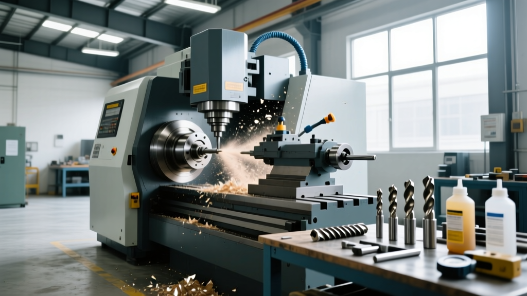
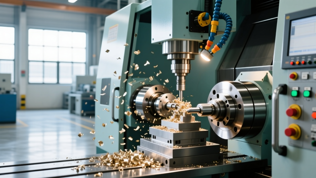
To accurately answer the question of what is the CNC machine, one must look past the basic acronym—Computer Numerical Control—and examine its function as a closed-loop, subtractive manufacturing system. At its core, a CNC machine translates digital CAD/CAM toolpaths into physical movements using G-code (specifically the RS-274D standard) and M-code auxiliary commands. Modern systems, such as those equipped with the Haas NGC or Siemens Sinumerik ONE controllers, utilize servo motors with high-resolution encoders to monitor axis position thousands of times per second, correcting micro-deviations in real-time.
However, defining the machine is only half the engineering challenge. The true value of understanding CNC technology lies in knowing when not to use it. In modern manufacturing, CNC machining competes directly with manual machining, metal additive manufacturing (3D printing), and non-traditional cutting like waterjet and laser. Choosing the wrong process can inflate part costs by 300% or result in catastrophic material failure under load.
CNC Machining vs. Manual Milling and Turning
Manual machining relies on the tactile skill of an operator using handwheels and digital readouts (DROs) on machines like the classic Bridgeport Series I mill or a manual South Bend lathe. CNC removes the human element from the cutting phase, replacing it with programmed automation. The decision between the two hinges entirely on production volume, geometric complexity, and tolerance requirements.
Warning: The Hidden Cost of CNC SetupBeginners often assume CNC is universally faster. For a single prototype requiring a simple facing operation and two drilled holes, a manual machinist can complete the part in 15 minutes. The same part on a CNC requires 45 minutes of CAM programming, tool setup, work coordinate system (WCS) probing, and first-article inspection. CNC only achieves a lower cost-per-part when amortizing setup time across a batch of 10 or more identical components.
Process Comparison Matrix: CNC vs. Manual
| Metric | CNC Machining (e.g., 3-Axis VMC) | Manual Machining (e.g., Knee Mill) |
|---|---|---|
| Standard Tolerance | ±0.0005" (±0.0127 mm) | ±0.002" to ±0.005" (±0.05 to ±0.127 mm) |
| Setup Time | 1 to 4 hours (Fixturing, Probing, CAM) | 10 to 30 minutes (Vise clamping, DRO zeroing) |
| Labor Rate (Operator) | $22 - $30 / hour (Machine Tender) | $35 - $55 / hour (Skilled Manual Machinist) |
| Complex Geometry | High (3D contours, blended radii) | Low (Linear tapers, simple arcs, 2D profiles) |
| Repeatability | Exact (Part 1 matches Part 1,000) | Variable (Subject to tool wear and operator fatigue) |
Subtractive CNC vs. Metal Additive Manufacturing (DMLS/SLM)
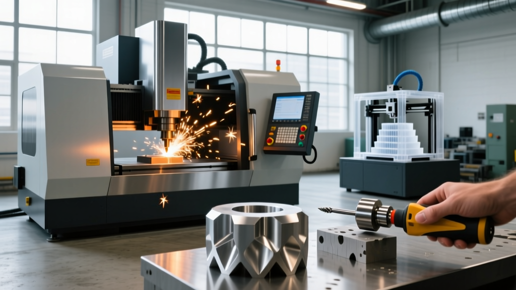
The rise of Direct Metal Laser Sintering (DMLS) and Selective Laser Melting (SLM) has forced a re-evaluation of what is the CNC machine's role in prototyping and aerospace manufacturing. Additive manufacturing builds parts layer by layer from metal powder, while CNC carves them from a solid billet or forging. According to research published by the Society of Manufacturing Engineers (SME), the choice between these two dictates the mechanical integrity of the final part.
Material Integrity and Isotropy
CNC machined parts are carved from wrought materials, such as 6061-T6 aluminum or 17-4 PH stainless steel. These materials possess an isotropic grain structure, meaning their tensile strength and yield limits are uniform across all axes. Conversely, DMLS 3D printed parts (using powders like AlSi10Mg or Inconel 718) are inherently anisotropic. The Z-axis (build direction) is typically 10% to 15% weaker than the X-Y plane due to the layer-by-layer thermal fusion process. If a part will experience high shear stress across the Z-axis, CNC machining from a solid billet is mandatory.
Surface Finish and Post-Processing
As-built DMLS parts exhibit a rough surface finish, typically measuring Ra 15 to 20 µm, due to partially fused powder particles adhering to the exterior. Achieving a CNC-milled standard finish of Ra 1.6 µm or better on a 3D printed part requires extensive secondary CNC machining or abrasive flow machining (AFM), which negates the time savings of printing. Furthermore, CNC machining easily holds tight geometric dimensioning and tolerancing (GD&T) callouts like true position within 0.001", whereas DMLS requires secondary machining to achieve any precision mating surfaces.
CNC Routing vs. Laser and Waterjet Cutting
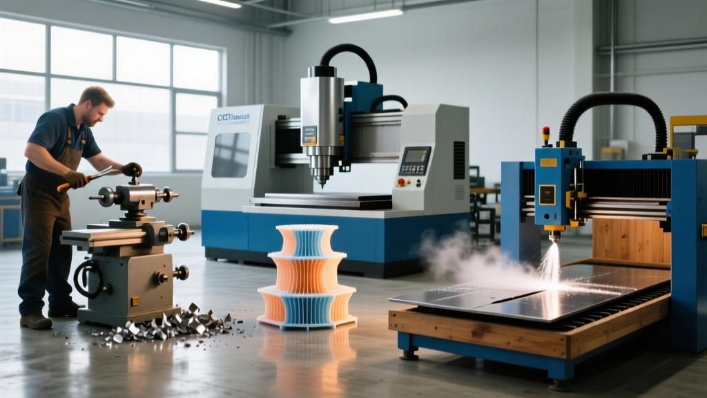
When manufacturing flat or 2.5D components from sheet metal or plate, engineers must decide between CNC milling/routing and thermal or kinetic cutting methods. Understanding the physical limitations of each process prevents costly design-for-manufacturing (DFM) errors.
- Fiber Laser Cutting: Ideal for thin sheets (up to 1" thick steel or aluminum). Lasers offer incredible speed and a narrow kerf width (0.004" to 0.008"). However, lasers cannot cut highly reflective materials like pure copper or brass without specialized wavelength adjustments, and they leave a heat-affected zone (HAZ) that can warp thin materials or alter the temper of hardened steels.
- Abrasive Waterjet Cutting: Capable of cutting up to 12" thick titanium or stone with zero HAZ. The trade-off is the 'kerf taper'—the waterjet stream naturally flares out, meaning the bottom of a 2" thick cut will be slightly wider than the top. While advanced 5-axis waterjet heads can compensate for this taper, it cannot match the perpendicularity of a CNC end mill.
- CNC Milling: Required when the part requires pockets, blind holes, threaded features, or precise 3D contouring. Unlike lasers and waterjets which only cut through-profiles, CNC end mills can remove material to specific depths, creating complex internal geometries and precise flat-bottomed pockets.
The 2026 Manufacturing Decision Framework
To synthesize these comparisons, use this practical decision tree when evaluating a new part design to determine if CNC machining is the correct process:
Process Selection Flowchart
- Does the part require internal 3D cavities, blind holes, or threads?
Yes: Use CNC Machining. (Lasers/Waterjets cannot create blind features; DMLS struggles with internal powder evacuation).
No: Proceed to step 2. - Is the production volume under 5 units with simple 2D geometry?
Yes: Use Manual Machining or Waterjet Cutting to avoid CAM programming and CNC setup costs.
No: Proceed to step 3. - Does the part feature complex internal lattice structures or conformal cooling channels?
Yes: Use Metal Additive Manufacturing (DMLS/SLM). CNC cannot reach internal enclosed geometries.
No: Proceed to step 4. - Are the tolerance callouts tighter than ±0.002" (±0.05 mm)?
Yes: Use CNC Machining. Additive and thermal cutting processes cannot hold these tolerances natively.
No: Evaluate Laser/Waterjet for speed and cost efficiency on sheet/plate profiles.
Ultimately, defining what is the CNC machine requires understanding it not as a standalone tool, but as the anchor of precision manufacturing. While 3D printing excels at geometric complexity and manual machining wins in rapid, low-volume prototyping, CNC machining remains the undisputed standard for producing high-strength, isotropic, and dimensionally exact components at scale. For further reading on advanced manufacturing tolerances and process standards, consult the guidelines provided by the National Institute of Standards and Technology (NIST) Advanced Manufacturing division.