What Is 5 Axis CNC Machining? An Operator's Training Guide
Master what is 5 axis CNC machining with this operator training guide covering RTCP, kinematics, tooling, and step-by-step first article run-offs.
Beyond the Basics: Defining 5-Axis Kinematics
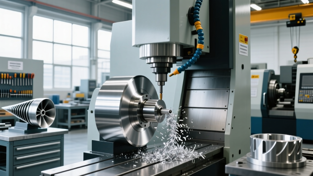
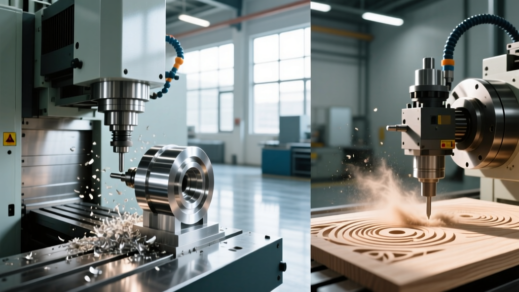
To answer the fundamental question of what is 5 axis CNC machining, we must look past the basic definition of simultaneous movement across five distinct axes (X, Y, Z, plus two rotational axes). For a CNC operator, 5-axis machining represents a shift from simple Cartesian milling to complex spatial vector management. In 2026, modern 5-axis VMCs (Vertical Machining Centers) and HMCs (Horizontal Machining Centers) rely on advanced servo-loop feedback to maintain sub-micron positional accuracy while the tool center point navigates compound angles.
Understanding the physical kinematic layout of your specific machine is the first step in operator training. Machines generally fall into two primary configurations:
1. Trunnion Style (Table/Table)
In a trunnion setup, both rotary axes (typically A and C) are mounted on the worktable. The spindle remains fixed in its vertical orientation. This is ideal for heavy, deep-cavity molds and large aerospace structural components because the table bears the payload weight directly. However, operators must account for the reduced Z-axis travel caused by the added height of the trunnion table and workholding.
2. Swivel Head Style (Head/Head or Head/Table)
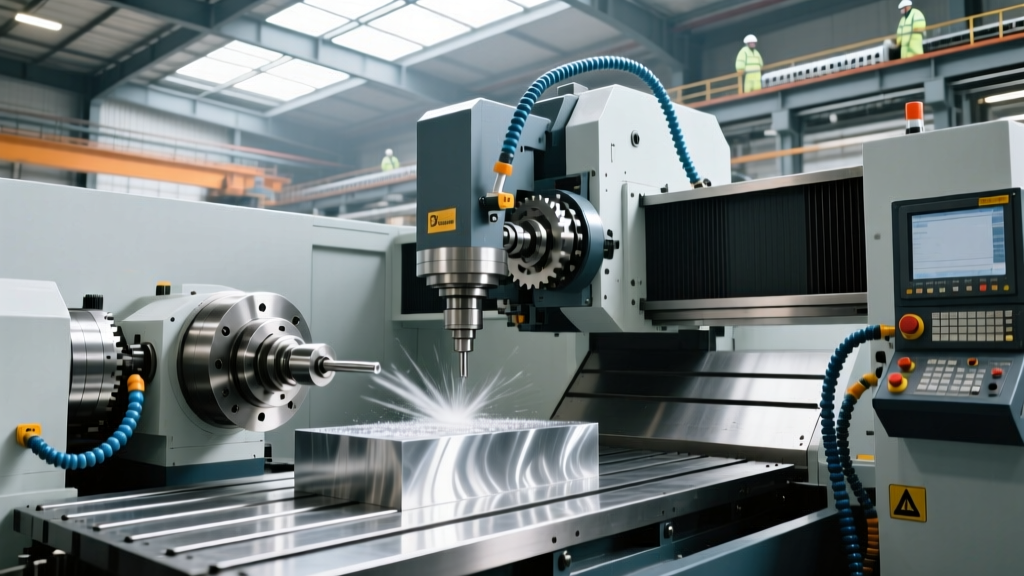
Here, the rotational axes (typically B and C, or A and C) are integrated into the spindle head. The table may only rotate (C-axis) or remain entirely static. Swivel head machines excel at machining tall, heavy parts that would cause a trunnion table to sag or exceed payload limits. Operators must be hyper-aware of spindle head collision zones, as the bulky 5-axis head assembly requires significantly more clearance around the part geometry.
"The transition from 3-axis to 5-axis isn't just about adding two rotary axes; it's about fundamentally rethinking tool approach vectors, tool overhang, and workholding rigidity."
3-Axis vs. 5-Axis: A Machinist’s Comparison Matrix
When training new operators, it is critical to illustrate why shops invest $150,000 to $300,000+ in 5-axis technology compared to the $45,000–$75,000 baseline of a standard 3-axis VMC. The ROI is found in setup reduction and tolerance retention.
| Metric | Standard 3-Axis VMC | Full 5-Axis VMC |
|---|---|---|
| Setup Count (Complex Part) | 3 to 5 distinct setups | 1 single setup (Done-in-One) |
| Tolerance Stack-Up | ±0.001" per flip (cumulative error) | ±0.0005" global (single WCS datum) |
| Tool Overhang Requirement | High (long reach tools needed for deep walls) | Low (table tilts to use short, rigid tools) |
| Surface Finish on Contours | Stair-stepping (ballnose limitations) | Smooth (flat-endmill side milling via tilt) |
| Operator Skill Ceiling | Moderate (2D/3D toolpath management) | Expert (collision avoidance, RTCP mastery) |
Critical Operator Training: Mastering RTCP
The most vital concept for a 5-axis operator to master is RTCP (Rotary Tool Center Point), also known as TCPC (Tool Center Point Control) depending on the controller brand (e.g., Fanuc, Siemens Sinumerik 840D sl, or Haas NGC).
When RTCP is active, the CNC controller dynamically compensates for the linear displacement caused by the rotation of the tilt axes. If you command the A-axis to tilt 30 degrees, the physical pivot point of the spindle moves in space. Without RTCP, the tool tip would gouge into the part or retract away from it. With RTCP enabled, the controller simultaneously commands micro-adjustments to the X, Y, and Z linear axes to ensure the exact tip of the cutting tool remains locked onto the programmed coordinate, regardless of the spindle's angular orientation.
⚠️ Operator Warning: RTCP VerificationNever run a 5-axis program without verifying RTCP state. If a CAM post-processor outputs absolute rotary moves assuming RTCP is OFF, but the machine has RTCP turned ON, the machine will execute massive, unintended linear shifts, resulting in a catastrophic crash. Always check your G-code header for the specific RTCP activation code (e.g., G43.4 on Fanuc, G234 on Haas) before cycle start.
Step-by-Step: The 5-Axis First Article Run-Off
Executing a first article on a 5-axis machine requires a rigorous, safety-first protocol. Follow this standardized run-off procedure to prevent crashes and verify kinematic accuracy.
- Verify Kinematic Calibration: Before loading the part, run an automated rotary axis calibration cycle. Using a spindle-mounted probe (like the Renishaw OMP60 or Blum MicroTouch), probe the calibration sphere on the trunnion or table. This updates the machine's internal kinematic model, compensating for thermal growth or mechanical shift since the last shift.
- Establish the 5-Axis WCS (Work Coordinate System): Use a 5-axis probing routine to find the part datum. Unlike 3-axis probing, a 5-axis routine will tilt the probe to measure undercut features or angled datums, establishing a highly accurate G54 coordinate system tied directly to the part's CAD model origin.
- Load and Verify Tool Length Offsets: 5-axis machining relies heavily on precise tool length and diameter data. A tool length error of just 0.005" can cause a severe gouge when the spindle is tilted at a 45-degree compound angle. Verify all tools using the machine's automatic tool setter.
- Execute a Z-Shifted Dry Run: Apply a global Z-axis work shift (e.g., +2.000") to lift the entire toolpath safely above the part and workholding. Run the program in single-block mode with rapid overrides set to 5%. Watch the distance-to-go screen and visually verify that the spindle head clears the trunnion, clamps, and part geometry during rotary transitions.
- Cut Air at Z-Zero: Remove the Z-shift and run the program with the spindle off and Z-axis locked (or use the machine's "machine lock" / "dry run" graphics verification) to confirm the final tool tip clearance.
Tooling & Workholding Best Practices for 5-Axis
Standard 3-axis tooling often fails in 5-axis environments due to the extreme side-loads and collision risks inherent to tilted spindle cutting.
Workholding: Zero-Point and Low-Profile
Because the spindle approaches from multiple angles, standard tall vises will cause collisions. Operators should utilize low-profile clamping solutions or Zero-Point clamping systems (such as System 3R or Schunk Vero-S). These systems allow the workpiece to sit mere millimeters above the table, maximizing Z-axis clearance and providing immense holding force for aggressive 5-axis roughing.
Toolholding: HSK and Shrink-Fit Dominance
While BT40 or CAT40 taper holders are fine for 3-axis face milling, 5-axis simultaneous machining demands superior radial rigidity and repeatability. According to Haas Automation's multi-axis specifications, high-speed 5-axis spindles perform best with dual-contact tooling or HSK-A63 tapers. Furthermore, operators should prioritize hydraulic expansion chucks or thermal shrink-fit holders for finishing operations. These holders provide superior concentricity (runout under 3 microns), which is critical when using long-reach endmills to machine deep, angled aerospace pockets.
Frequently Asked Questions for New 5-Axis Operators
What causes a 'Kinematic Singularity' in 5-axis toolpaths?
A singularity occurs when the toolpath demands an axis movement that the machine's physical kinematics cannot mathematically resolve, often resembling 'gimbal lock.' For example, on a B/C head machine, if the B-axis is at exactly 0 degrees (straight down), the C-axis rotation becomes undefined. Modern CAM software and controllers (as noted in NIST Advanced Manufacturing guidelines) include singularity avoidance algorithms that slightly tilt the tool vector (e.g., to 0.5 degrees) to maintain smooth, continuous servo movement without erratic axis spikes.
How does 5-axis machining improve tool life?
By tilting the tool or the table, operators can maintain a constant, optimal chip thickness and avoid cutting with the dead center (zero surface speed) of a ballnose endmill. Additionally, tilting allows the use of shorter, stubbier endmills to reach deep features, drastically reducing tool deflection, chatter, and premature edge wear.
Can I use a standard 3-axis CAM post for 3+2 machining?
No. Even for 3+2 machining (where the rotary axes lock into position before the 3-axis cut begins), you must use a dedicated 5-axis post-processor. The post-processor must calculate the specific rotary angles required to align the tool vector normal to the tilted workplane, outputting the correct A/B/C coordinates and WCS rotation codes (like G68.2 Tilted Working Plane) that a standard 3-axis post cannot generate.