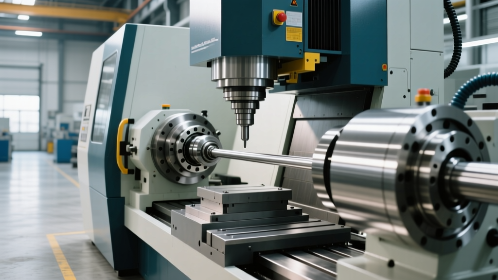
Troubleshooting Machine and Machine Tool Rigidity and Vibration
Diagnose and fix chatter, deflection, and harmonic vibration in your machine and machine tool setups with this advanced troubleshooting framework.
Unplanned downtime caused by chatter marks, poor surface finishes, and accelerated insert wear rarely stems from a single faulty component. In precision manufacturing, these symptoms are the direct result of compromised structural stiffness and unmanaged harmonic frequencies. When troubleshooting a machine and machine tool assembly, technicians must evaluate the entire kinematic chain—from the concrete foundation and way covers to the spindle taper and cutting edge.
This guide provides a systematic, data-driven framework for isolating rigidity failures and diagnosing vibration modes in vertical machining centers (VMCs), horizontal boring mills (HBMs), and CNC lathes.
The Physics of Deflection: Why Rigidity Dictates Tolerance
Rigidity is the resistance of a mechanical system to elastic deformation under load. In machining, the total system deflection ($\delta_{total}$) is the sum of deflections across the machine structure, the toolholder, and the cutting tool. Because deflection in a cylindrical tool increases with the cube of its overhang length ($L^3$), a tool extending just 20% further from the spindle face will deflect 72% more under the exact same cutting forces.
Shop Floor Reality Check: A standard 3/4-inch solid carbide end mill with a 3-inch stickout subjected to 150 lbs of radial cutting force will deflect approximately 0.0015 inches. If you double the stickout to 6 inches to reach a deep pocket, that same tool will deflect 0.012 inches—destroying your tolerance and triggering violent chatter.To combat this, modern machining relies on maximizing the damping coefficient of the machine and machine tool interface. While steel and cast iron provide static stiffness, materials like epoxy granite and polymer concrete offer up to 10 times the vibration damping capacity of traditional cast iron, absorbing high-frequency harmonics before they reach the workpiece.
Diagnostic Decision Tree: Isolating the Vibration Source
Before replacing expensive spindle bearings or scrapping parts, use this diagnostic matrix to pinpoint the exact node of failure in your setup.
| Observed Symptom | Frequency / Audio Signature | Probable Root Cause | Immediate Corrective Action |
|---|---|---|---|
| Uniform chatter marks across entire surface | High-pitched squeal (>1,000 Hz) | Tool/Holder Regenerative Chatter | Reduce radial depth of cut (ae); switch to variable helix end mill. |
| Localized surface waviness / lobing | Low-frequency hum (50 - 300 Hz) | Spindle Bearing Wear or Drive Belt Slippage | Perform a tap test; check spindle runout with a dial indicator,0.0002" TIR). |
| Dimensional taper / size variation in Z-axis | Silent / No audible vibration | Thermal Growth or Ballscrew Backlash | Warm up spindle for 20 mins; check axis reversal error via laser interferometer. |
| Random, unpredictable tool breakage | Intermittent clunking or banging | Loose Workholding or Foundation Shift | Torque fixture bolts to spec; verify leveling pads are fully seated. |
Step-by-Step Troubleshooting: The Toolholder and Spindle Interface
Over 60% of rigidity complaints traced back to the "machine and machine tool" connection occur at the spindle taper. A microscopic layer of debris or a worn retention knob can reduce effective stiffness by half.
1. Inspect the Retention Knob (Pull Stud)
The retention knob is the critical link pulling the toolholder into the spindle taper. If the knob is stretched or the wrong thread pitch is used, the toolholder will sit slightly proud of the spindle nose.
- The Test: Apply layout fluid (Dykem Blue) to the spindle taper. Insert the toolholder and clamp it. Remove and inspect the blue transfer.
- The Standard: You must see a minimum of 85% contact area on the front two-thirds of the taper. If contact is concentrated only at the flange (the large end), your retention knob is incorrect or the spindle drawbar is weak.
- The Fix: Replace the knob with a high-precision, spindle-specific model (e.g., Techniks or Parlec). Never mix metric and imperial pull studs, as a 1.5mm pitch in a 1.75mm threaded drawbar will strip the internal spindle threads under 2,500 lbs of clamping force.
2. Evaluate Toolholder Technology for Your RPM
Not all toolholders provide equal rigidity. As shops push toward 15,000+ RPM to utilize modern coated carbides, standard Weldon (setscrew) and ER collet chokers become liabilities due to poor concentricity and grip strength.
Warning on Hydraulic Holders: While hydraulic chucks offer excellent damping for finishing operations, they are prone to internal fluid cavitation and grip failure during heavy roughing (e.g., trochoidal milling in titanium). For heavy radial loads, always default to high-quality shrink-fit or mechanical milling chucks like the HAIMER Power Mill.Advanced Vibration Analysis: Tap Testing and Stability Lobe Diagrams
When basic mechanical checks fail to resolve chatter, you must map the dynamic stiffness of the system. According to research published by the National Institute of Standards and Technology (NIST), empirical tap testing is the most reliable method for predicting machining stability.
How to Perform a Shop-Floor Tap Test
- Instrument Setup: Mount a miniature accelerometer (e.g., PCB Piezotronics model 352C23) to the tip of the cutting tool using a small dab of beeswax or magnetic base.
- Impact Excitation: Strike the tool with an instrumented impact hammer equipped with a soft polymer tip to excite frequencies up to 5,000 Hz without damaging the carbide.
- Data Capture: Record the Frequency Response Function (FRF) using a portable analyzer or software like CUTPRO.
- Generate the SLD: The software calculates a Stability Lobe Diagram (SLD), which maps spindle speed (RPM) against axial depth of cut. The "lobes" identify the exact RPM windows where the natural frequency of the tool harmonizes with the tooth-passing frequency, allowing you to take drastically deeper cuts without chatter.
By utilizing SLDs, aerospace manufacturers routinely increase material removal rates (MRR) by 30% to 50% in deep-pocket milling simply by shifting the spindle speed to a stable node, rather than buying stiffer, more expensive tooling. For deeper insights into harmonic mapping, Sandvik Coromant's milling vibration guides provide excellent baseline formulas for calculating tooth-passing frequencies.
Machine Structure and Foundation Troubleshooting
If the tool and holder are verified rigid, the vibration is originating from the machine structure or the floor. CNC machines weighing 15,000+ lbs are highly sensitive to environmental vibrations from nearby stamping presses, forklift traffic, or improper leveling.
Verifying Level and Foundation Integrity
A machine resting on a cracked concrete slab or improper leveling pads will twist the base casting. This twist misaligns the linear guideways, causing the axis drives to fight against binding friction, which manifests as low-frequency stick-slip vibration.
- Leveling Protocol: Use a 0.0005"/10" precision master level. Check the machine table in the X and Y axes at the center of travel and all four quadrants.
- Pad Selection: Replace hardened steel point-contacts with elastomeric or air-spring isolators (e.g., Fabreeka pads) if the shop floor suffers from constant transient shock loads. Elastomeric pads tune the natural frequency of the machine below 5 Hz, effectively decoupling it from floor vibrations that typically range from 10 to 30 Hz.
- Anchor Bolts: For heavy HMCs and 5-axis trunnion machines, chemical anchor bolts (epoxy-grouted) into a minimum 12-inch thick reinforced concrete pad are mandatory. Relying solely on leveling pads for a machine generating 2,000 lbs of cutting thrust will result in gradual walking and geometry loss.
Optimizing Workholding for Maximum Damping
The workpiece itself is often the weakest link in the rigidity chain. Thin-walled components and unsupported overhangs act as tuning forks.
"When clamping force is insufficient to overcome cutting forces, the part micro-lifts off the fixture locators. This creates a high-frequency impact that sounds exactly like tool chatter, leading mechanics to blame the spindle when the fixture is actually at fault." — Senior Manufacturing Engineer, Tier 1 Aerospace Supplier.
Actionable Fixes for Part Vibration:
- Hydraulic Fixturing: Upgrade to hydraulic clamping to ensure consistent, repeatable clamping force. Manual toggle clamps can vary by 20% depending on the operator's strength and fatigue.
- Low-Melt Alloys & Epoxies: For complex, thin-walled castings (like impellers), use Cerrobend (a bismuth-based low-melt alloy) or specialized fixture epoxies to fill the voids between the part and the fixture base. This provides 100% support across the entire underside of the part, virtually eliminating part-induced chatter.
- Strategic Toolpaths: Utilize CAM software features like "Trochoidal Milling" or "Dynamic Motion" (Mastercam). These toolpaths maintain a constant radial engagement angle and chip thickness, preventing the sudden spikes in cutting force that break static friction and initiate vibration.
Mastering the interplay between static stiffness and dynamic damping is what separates average shops from world by utilizing tap testing, verifying spindle taper contact, and securing the foundation, you ensure that your machine and machine tool investments yield the precision and profitability they were engineered to deliver.